CLI: Example for Configuring ESP NAT in a NAT Server Scenario
Networking Requirements
A user on LAN 2 proactively accesses LAN 1. For information transmission security, an IPSec tunnel shall be established between the LANs. However, devices on the LANs, such as PCs, do not support the NAT traversal function, and UDP headers cannot be used to encapsulate ESP packets. Therefore, faults may occur during NAT for ESP packets without port numbers. The FW maps the address of the PC on LAN 1 to a public address through the NAT Server. When a user on LAN 2 proactively accesses LAN 1, the FW translates the destination address to the address of the PC on LAN 1 and sets the port number for the ESP session to differentiate various ESP packets, so that the IPSec tunnel can be successfully established.
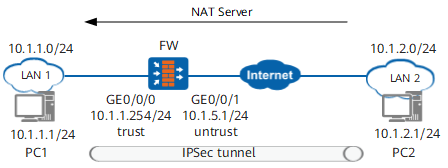
Figure 1 shows the networking:
LAN 2 belongs to subnet 10.1.2.0/24 and connects to the Internet.
- The FW serves as the NAT device, and the private address on LAN 1 is mapped to a public address through NAT Server for the user on LAN 2 to access. The enterprise applies for one IP address (1.1.1.10) towards the ISP as the public address.
Data Planning
Item |
Data |
|---|---|
| Devices on LAN 1, such as PC1 | IPSec configuration Peer address: 10.1.2.1 Authentication mode: pre-shared key Pre-shared key: Test!1234 Local ID type: IP address Peer ID type: IP address Peer ID: 10.1.2.1 IPSec encapsulation mode: transport mode |
| FW | NAT server configuration Internal address: 10.1.1.1 Public address: 1.1.1.10 |
| Devices on LAN 2, such as PC2 | IPSec configuration Peer address: 1.1.1.10 Authentication mode: pre-shared key Pre-shared key: Test!1234 Local ID type: IP address Peer ID type: IP address Local ID: 10.1.2.1 IPSec encapsulation mode: transport mode |
Procedure
- Detailed configurations of PC1 and PC2 are not described in this example.
Huawei FW supports NAT traversal. If Huawei FW is used to establish an IPSec tunnel, you do not need to configure ESP NAT. You need to enable ESP NAT on the intermediate NAT device only when the IPSec initiator and recipient do not support NAT traversal.
- Configure interfaces, security policies, and routes for the FW.
- Configure security policies.

The source and destination addresses of security policies are the addresses of both ends of the IPSec tunnel. If the gateway device exists between the FW and LAN 1 as well as in front of the Internet and LAN 2, and the IPSec tunnel is established on the gateway device, the match conditions of security policies shall be modified.
[FW] security-policy
[FW-policy-security] rule name policy1
[FW-policy-security-rule-policy1] source-zone untrust
[FW-policy-security-rule-policy1] destination-zone trust
[FW-policy-security-rule-policy1] source-address 10.1.2.0 24
[FW-policy-security-rule-policy1] destination-address 10.1.1.0 24
[FW-policy-security-rule-policy1] action permit
[FW-policy-security-rule-policy1] quit
- Configure security policies.
- Configure ESP NAT and NAT Server.
Configuration Scripts
Configuration script for the FW:
#
 sysname FW
#
interface GigabitEthernet 0/0/0
  ip address 10.1.1.254 255.255.255.0
#
interface GigabitEthernet 0/0/1
 ip address 10.1.5.1 255.255.255.0
#
firewall zone trust
 set priority 85
 add interface GigabitEthernet 0/0/0
#
firewall zone untrust
 set priority 5
 add interface GigabitEthernet 0/0/1
#
security-policy
  rule name policy1
    source-zone untrust
    destination-zone trust
    source-address 10.1.2.0 24
    destination-address 10.1.1.0 24
    action permit
#
firewall esp nat enable
#
nat server espnat1 protocol 50 global 1.1.1.10  inside 10.1.1.1
#
return