BFD Packet
This section describes the format of the BFD packet.
BFD packets fall into two types, namely, BFD control packet and BFD echo packet.
BFD Control Packet
BFD control packets are encapsulated in UDP packets for transmission, and the destination port of UDP is port 3784.
A BFD control packet consists of a mandatory part and an optional authentication part. Figure 1 shows the format of the BFD control packet.
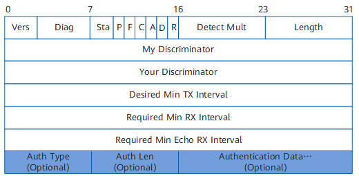

FW does not support the BFD function.
Table 1 shows the description of each field in the packet.
Field |
Length |
Description |
|---|---|---|
Vers (Version) |
3 bits |
Indicates the version number of the protocol. The current version number is 1. |
Diag (Diagnostic) |
5 bits |
Indicates the cause that the status of the latest session changes from Up to other status in the local system. Different values indicate different causes:
|
Sta (State) |
2 bits |
Indicates the status of the current BFD session. Different values indicate different statuses:
|
P (Poll) |
1 bit |
Indicates the bit for connection request confirmation. Different values indicate different meanings:
|
F (Final) |
1 bit |
Indicates the bit determining whether the sending system responds to a BFD control packet with P bit as 1. Different values indicate different meanings:
|
C (Control Plane Independent) |
1 bit |
Indicates the bit determining whether BFD control packets are transmitted on the control plane. Different values indicate different meanings:
|
A (Authentication Present) |
1 bit |
Indicates the bit determining whether BFD control packets contain the authentication field. Different values indicate different meanings:
NOTE:
FW does not provide the BFD authentication function currently. The A bit is set to 0 all the time. |
D (Demand) |
1 bit |
Indicates the demand mode operation bit. Different values indicate different meanings:
|
R (Reserved) |
1 bit |
This field is set to 0 when a BFD control packet is sent. This field is ignored when a BFD control packet is received. |
Detect Mult (Detect time multiplier) |
1 byte |
Indicates the detection time multiplier, that is, the maximum number of continuous loss of packets permitted by the packet receiver. The bit is used to check whether the link is normal.
|
Length |
1 byte |
Indicates the length of a BFD control packet, in bytes. |
My Discriminator |
4 bytes |
Indicates a unique non-zero discriminator value generated by the sending system. The value is used to differentiate multiple BFD sessions of a system. |
Your Discriminator |
4 bytes |
Indicates the value of My Discriminator sent from the remote system. If this value is not received, the field is set to 0. |
Desired Min Tx Interval |
4 bytes |
Indicates the desired minimum interval for sending BFD control packets by the local system, in microseconds. |
Required Min Rx Interval |
4 bytes |
Indicates the minimum interval required between receiving two BFD control packets, in microseconds. |
Required Min Echo Rx Interval |
4 bytes |
Indicates the minimum interval required between receiving two BFD echo packets, in microseconds. If the interval is set to 0, the sending system cannot receive BFD echo packets. |
Auth Type |
1 byte |
Indicates the authentication type of BFD control packets. Different values indicate different authentication types:
|
Auth Len |
1 byte |
Indicates the length of the authentication field, including the authentication type field and the authentication length field, in bytes. |
Authentication Data |
2 bytes |
Indicates the authentication data. |
BFD Echo Packet
BFD echo packets provide a fault detection mechanism independent from BFD control packets. The local end sends and receives the packets. The peer end returns the packets over the reverse channel without processing the packets. Therefore, the format of BFD echo packet is not defined by the BFD protocol. The only requirement is that the sender can distinguish sessions according to packet contents.
BFD echo packets are encapsulated in UDP packets for transmission. The destination port number is 3784. The destination IP address is the address of the sending interface. The source IP address is specified manually.