Application Scenarios for Bandwidth Management
This section describes the application scenarios of bandwidth management.
Maximum Bandwidth, Guaranteed Bandwidth, and Connection Limit for Bandwidth Management on Enterprise Networks
Figure 1 shows the typical application scenario of bandwidth management. On office networks, email and ERP traffic is key service traffic, and P2P and online video traffic is non-key service traffic. However, the limited network bandwidth resources of enterprise networks are always occupied by non-key service traffic, and the transmission of key service traffic is not guaranteed. As a result, normal services are affected.
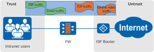
The overall maximum bandwidth and overall guaranteed bandwidth functions that the FW provides can effectively prevent non-key service traffic from occupying too many bandwidth resources and ensure that key service traffic can be properly forwarded during peak hours. In addition, the FW provides the connection limit function to facilitate P2P traffic control.
Per-IP-Address or Per-User Maximum Bandwidth for Bandwidth Management on Each IP Address or User on the Enterprise Networks
As shown in Figure 2, Source NAT is configured for enterprise employees to access the Internet, and NAT Server is configured for the intranet servers to provide services for external users. The enterprise egress provides limited bandwidth, but a small number of users occupy a large amount of bandwidth, and some intranet servers also occupy a great amount of bandwidth to provide services for external users. As a result, the enterprise network operation is severely impacted.
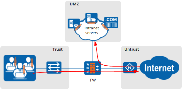
The bandwidth management function that the FW provides allows you to configure the maximum bandwidth resources for each user or for each intranet server to provide services for external users when Source NAT or NAT Server is enabled. As a result, granular bandwidth management and control are implemented.
Public IP Address Matching for Bandwidth Management on the Public IP Addresses After Source NAT or Before NAT Server
As shown in Figure 3, Source NAT is configured for enterprise employees to access the Internet, and NAT Server is configured for the intranet servers to provide services for external users. Because the enterprise network has limited egress bandwidth, administrators require to restrict the bandwidth for specific public IP addresses but not the bandwidth for each employee or server.

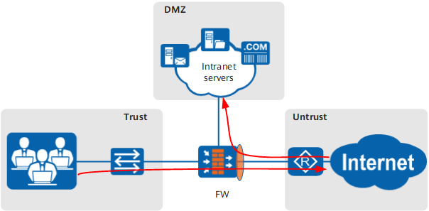
The bandwidth management function that the FW provides can restrict the bandwidth for the public IP addresses after Source NAT or before NAT Server to implement overall bandwidth control.
Hierarchical Traffic Policies for Bandwidth Management on a Specific Department or on the Employees and Services of That Department
As shown in Figure 4, the enterprise has departments A and B, and department A has R&D and sales employees. The enterprise requires that hierarchical management and control be implemented on existing bandwidth resources to restrict the bandwidth of departments A and B as well as the R&D and sales employees in department A. The enterprise also requires that key application traffic, such as email and ERP traffic be properly forwarded during traffic peak hours to ensure that the sales employees in department A can conduct daily businesses properly.
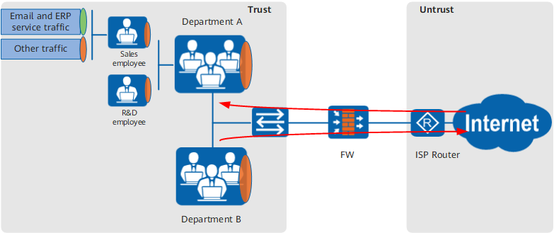
The bandwidth management function that the FW provides can use hierarchical traffic policies to control the bandwidth of a specific department or specified employees and services in that department.
Shared Traffic Profile for Multi-Dimensional Bandwidth Management on One Object
As shown in Figure 5, the enterprise has departments A and B. Respective bandwidth controls must be implemented on the two departments. In addition, P2P applications occupy a great amount of bandwidth. Therefore, the enterprise requires that a limit be set to limit the total P2P application bandwidth shared by departments A and B.
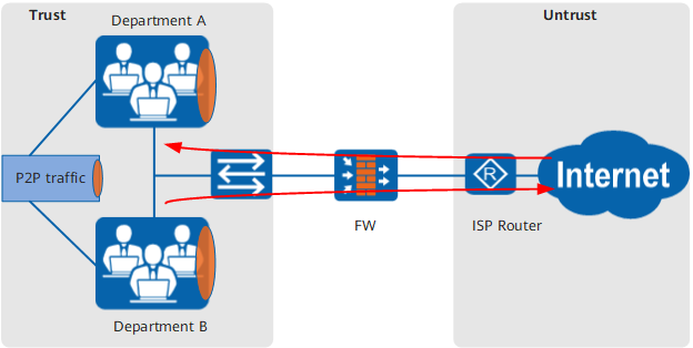
The bandwidth management function that the FW provides allows you to configure shared traffic profiles for each department to have separate traffic policies and to limit the P2P traffic across departments to implement multi-dimensional bandwidth management.
Dynamic Even Distribution of Bandwidth Resources for Each User
As shown in Figure 6, the number of online users of a department is not fixed. To prevent some employees from exclusively occupying the limited bandwidth resources, you can evenly and dynamically distribute the bandwidth resources to the online users.
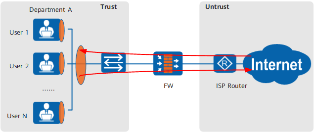
The traffic management function that the FW provides allows you to configure a maximum overall bandwidth for all employees and then dynamically calculates the available maximum bandwidth resources for each user based on the number of online IP addresses or users.
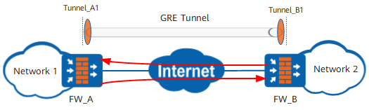
Interface Bandwidth for Bandwidth Management on Tunnel Interface Traffic on Both Ends of the GRE Tunnel
As shown in Figure 7, network 1 and network 2 establish GRE tunnels in between. You can configure interface bandwidth for bandwidth management on tunnel interface traffic on both ends of the GRE tunnel. Then bandwidth management and control are implemented on the total traffic transmitted on the Internet after GRE encapsulation. For GRE and tunnel interface configurations, see GRE and Interfaces. You can use either of the following modes to implement bandwidth management and control on the tunnel interface:
- Choose and set the upstream and downstream bandwidth of the tunnel interface.
- Reference the tunnel interface in matching condition Inbound/Outbound Interface of the traffic policy. For details, see Configuring a Traffic Policy.