Understanding Bypass
This section describes the background and basic principles of hardware bypass.
If a FW is deployed on a network in in-line mode, once the FW stops functioning, the network services are interrupted, and enormous consequences may occur. Sometimes, the loss is disastrous.
To minimize the impact of this failure and improve network reliability, the FW provides a bypass interface pair to implement the hardware bypass function. When the FW is powered off or reboot, the bypass interface pair directly connects to the upstream and downstream devices. In this way, the traffic directly passes through the FW without detection or blocking, and the services are not interrupted. After the FW recovers, the traffic is taken over by the FW for processing and forwarding, and the traffic security is restored.
Hardware Bypass State
As shown in Table 1, the bypass interfaces have two states.
State |
Description |
|---|---|
Bypass |
When the interfaces are in bypass state, the upstream and downstream devices are connected directly by a pair of bypass interfaces, and traffic is not processed by the local device. |
Non-bypass |
When the interfaces are not in bypass state, a pair of bypass interfaces is not directly connected, and traffic is processed by the local device. |
As shown in Figure 1, GE0 and GE1 are a pair of bypass interfaces. GE0 connects to Router_A and GE1 to Router_B to form a bypass link.
- When interfaces work in non-bypass state, the traffic flows from Router_A to the FW through GE0. After the processing is complete, the traffic flows from GE1 on the FW to Router_B. The reverse also works.
- When interfaces work in bypass state, the traffic flows from Router_A to the FW through GE0. Then the traffic directly flows to Router_B through GE1 without being processed by the FW. This is equivalent to a direct connection between Router_A and Router_B.
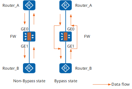
Hardware Bypass Triggers
The bypass interfaces will work in the bypass state in the scenarios shown in Table 2 to implement the hardware bypass function.
Trigger |
Trigger Type |
Description |
|---|---|---|
Power loss |
Hardware automatic bypass |
- |
System expection |
Hardware automatic bypass |
Reboot caused by software-agnostic system abnormality. |
Software-aware reboot |
Software automatic bypass |
Includes the reboot command, a fatal fault that can be sensed by the software, or upgrade. |
Software-aware hardware fault |
Software automatic bypass |
When the device is running properly and detects that the hardware link corresponding to the bypass interface is faulty, the device automatically switches to the bypass state. |
Manual trigger |
Manual bypass by administrator |
The administrator runs the switch bypass command to manually trigger bypass during the device is powered on and running. |