Configuring a DS-Lite Tunnel
A DS-Lite tunnel is used to transfer packets between a private IPv4 network and a public IPv4 network over an IPv6 network.
Prerequisites
To configure a DS-Lite tunnel, the FW must support the DS-Lite feature and be configured as follows:
- IPv6 packet forwarding is enabled globally.
- An IPv6 address is configured for the interface that is connected to the IPv6 network, the interface is up, and the IP connectivity to the IPv6 address is established.
Context
As shown in Figure 1, both the CPE and the FW are on the edge between the IPv4 and IPv6 networks, and support dual stacks. A DS-Lite tunnel is configured between the CPE and the FW, so that packets from the private IPv4 users under the CPE can reach the FW over an IPv6 network.
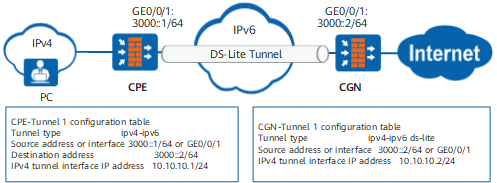
Note the following in configuring a DS-Lite tunnel on the CPE and the FW:
The CPE can be configured to support common IPv4-over-IPv6 tunnels, whereas the FW must be configured to support ipv4-ipv6 ds-lite encapsulation.
The destination address of the tunnel must be specified on the CPE, but is unnecessarily to be specified on the FW. This is because the CGN device can find the destination IP address of the tunnel based on the CPE IP address in the session table or server map table.
A route for the tunnel must be configured on the CPE to ensure proper packet forwarding. On the FW, however, a route for the tunnel is unnecessary because packets can be routed from the FW back to the CPE based on CPE IP and Tunnel ID in the session table or server map.
Perform the following configurations on the FW.
Procedure
- Access the system view.
- Create a tunnel interface and access the tunnel interface view.
interface tunnel interface-number
- Set the encapsulation mode of the tunnel to DS-lite.
tunnel-protocol ipv4-ipv6 ds-lite
- Specify the source address or interface of the tunnel.
source { source-ipv6-address | interface-type interface-number }

- You can specify the IPv6 address of the interface that is connected to the IPv6 network as the source address of the DS-Lite tunnel, or directly specify the interface as the source interface.
- You can specify either a physical interface or a logical interface, such as the loopback interface, as the source interface of the tunnel.

If the source of the DS-Lite tunnel interface is specified as an interface, and multiple IPv6 addresses are configured for the interface, only the first specified IPv6 address can be used as the destination IP address for the peer CPE. After running the display this command on this interface, the first IPv6 address is displayed.
- Set an IPv4 address for the tunnel interface.
ip address ip-address { mask | mask-length }
- (Optional) Enable the function of copying the Traffic Class tag of each IPv6 packet before decapsulation to the DSCP tag of the IPv4 packet after the decapsulation.
Traffic Class tag and DSCP tag set the priority of a data flow. The priority value ranges from 0 to 63 for both IPv6 and IPv4 packets. The DS-Lite tunnel bridges data flows to an IPv4 network over an IPv6 network. To maintain the original processing priorities of data flows, you can run this command to copy the priority of IPv6 data flows before decapsulation to that of IPv4 data flows after the decapsulation.
Example
As shown in Figure 1, the CPE, is connected to the FW through an IPv6 network. The IPv6 address of GigabitEthernet 0/0/1, the interface between the CPE and the IPv6 network, is 3000::1/64. The IPv6 address of GigabitEthernet 0/0/1, the interface between the FW and the IPv6 network, is 3000::2/64. A DS-Lite tunnel is established between the CPE and the FW.
# Configure the encapsulation type, source address, and IPv4 address of the tunnel interface for the FW.
<CGN> system-view
[CGN] ipv6
[CGN] interface tunnel 1
[CGN-Tunnel1] tunnel-protocol ipv4-ipv6 ds-lite
[CGN-Tunnel1] source 3000::2
[CGN-Tunnel1] ip address 10.10.10.2 24
# Configure the encapsulation type, source address, destination address, and IPv4 address of the tunnel interface for the CPE.
<CPE> system-view
[CPE] ipv6
[CPE] interface tunnel 1
[CPE-Tunnel1] tunnel-protocol ipv4-ipv6
[CPE-Tunnel1] source 3000::1
[CPE-Tunnel1] destination 3000::2
[CPE-Tunnel1] ip address 10.10.10.1 24
# Configure a route for the tunnel from the CPE to the FW.
[CPE] ip route-static 0.0.0.0 0.0.0.0 Tunnel 1
Follow-up Procedure
After the configuration, run the display interface tunnel command in any view of the FW to view the tunnel status and configuration information.
<CGN> display interface tunnel1
Tunnel1 current state : UP
Line protocol current state : UP
Last line protocol up time : 2011-07-13 01:01:53
Description: Series, Tunnel1 Interface
Route Port,The Maximum Transmit Unit is 9600
Internet Address is 10.10.10.2/24
Encapsulation is TUNNEL6, loopback not set
Tunnel Source 3000::2 (GigabitEthernet 0/0/1)
Tunnel Destination ::
Tunnel Encapsulation limit 1
Tunnel Traffic class not set
Tunnel Flow label not set
Tunnel Hop limit 64