Understanding PCP
This section describes the PCP mechanism.
PCP Connection and PCP Mapping Table
Figure 1 shows the PCP connection negotiation process.
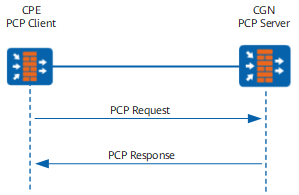
- The CPE sends to the CGN a PCP request for a public IP address and a public port number for private network user access.
- Upon receipt, the CGN (FW) selects a public IP address from the NAT address pool and generates a NAT entry containing the mapping between the private IP address and port number and the public IP address and port number. The CGN then sends a PCP response packet carrying the requested public IP address and port number to the CPE.
A PCP negotiation can be carried out in either the peer or map mode. Different PCP requests are involved in different modes. After receiving a PCP request from the CPE, the FW generates a PCP mapping entry based on the specified PCP negotiation mode.
Peer mode
After receiving a request in a peer mode from the CPE, the FW parses the request, assigns the public IP address and port number from the NAT address pool to the user, and generates the following PCP mapping entry:
Type: PEER,    Protocol: UDP, Zone: ---, Vpn: public
 192.168.0.10:17192[1.1.1.3:9000] -> 2.2.2.10:1280
 TTL: 1800, Left: 1800, Pool: 30, Section: 1
 Mapping Nonce: 0x353137383539353136000000
The PCP mapping entry includes a source address, source port number, destination address, destination port number, and protocol, and is a 5-tuple entry. In the peer mode, private network users can access the Internet, but Internet users cannot proactively communicate with private network users. Therefore, the peer mode is not applicable to P2P services.
In the peer mode, the PCP client can send a new PCP request to keep the PCP mapping entry alive after its TTL expires.
Map mode
After receiving a request in map mode from the CPE, the FW parses the request, assigns the public IP address and port number from the NAT address pool to the access user, and generates the following PCP mapping entries:
Type: MAP IN,  Protocol: TCP, Zone: ---, Vpn: public
 ANY -> 1.1.1.3:2048[192.168.0.10:5791]
 TTL: 120, Left: 120, Pool: 10000, Section: 0
 Mapping Nonce: 0x000000000000000032142158, Filter(s): 0

 Type: MAP OUT, Protocol: TCP, Zone: ---, Vpn: public
 192.168.0.10:5791[1.1.1.3:2048] -> ANY
 TTL: 120, Left: 120, Pool: 10000, Section: 0
 Mapping Nonce: 0x000000000000000032142158, Filter(s): 0
The MAP IN and MAP OUT entries include the source address, source port number, and protocol fields and are 3-tuple entries, similar to server-map entries generated by 3-tuple NAT. The Internet user can proactively communicate with the private network user based on the MAP IN entry. Therefore, the map mode is applicable to P2P service scenarios.
After a PCP mapping entry in map mode is generated, if you want to keep the entry alive after its TTL times out, the PCP client can send a PCP request to renew the TTL of the PCP mapping entry.
In addition, the CGN or FW supports the ANNOUNCE response mode, in which the restarted CGN or FW notifies the CPE of rapidly restoring PCP mappings.
PCP and P2P Services
PCP is applied in a NAT444 scenario for P2P service transmission among users. Figure 2 shows the application of PCP in P2P services.
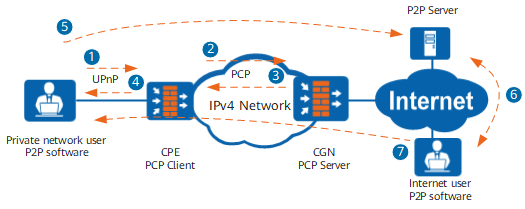

The PC of the private network user must support the Universal Plug and Play (UPnP) protocol. You are advised to use UPnP-capable P2P software.
The process for applying PCP in P2P services is as follows:
- The private network user starts P2P software so that the software can automatically send a UPnP request packet to instruct the CPE to open a User Datagram Protocol (UDP) listening port.
- Upon receipt, the CPE performs the following operations:
- Uses the UPnP proxy function to accept the UPnP request and triggers the PCP client function.
- Uses the PCP client function to send the CGN a PCP request for a public IP address and a public port number.
- Upon receipt, the CGN selects a public IP address from the NAT pool and generates a NAT entry containing the mapping between the private IP address and port number and the public IP address and port number. Then the CGN sends a PCP response packet carrying the requested public IP address and port number to the CPE.
- The CPE forwards the public IP address and port number to the private network user. The public IP address and port number can be viewed in the P2P software.
- The private network user uses the public IP address and port number to access the P2P server to report its connection status in real time. The P2P server records the public IP address and port number.
- When the Internet user sends a request for a file to the P2P server, the P2P server replies with all the file owners' information, including file owners' public IP addresses and port numbers.
- The Internet user uses the public IP address and port number to proactively communicate with the private network user and download required files.