Understanding Port Pre-allocation and Incremental Allocation
This section describes the mechanism for port pre-allocation and incremental allocation.
On NAT444 networks, if port pre-allocation is not applied, each data flow generates a log. In the case of massive service amount, a huge number of logs are generated on the CGN and received by the log server, which compromises the data source tracing efficiency of the log server.
After port pre-allocation is enabled, the CGN generates a log when a port range is allocated and another log when the port range is recycled, which greatly reduces the number of logs. In this way, the efficiency of data source tracing is improved.
After the pre-allocated port range for the CPE is used up, incremental allocation allocates new port resources for a maximum of three times. This function flexibly allocates port resources to effectively cope with the drastic increase of services on the CPE.
Port pre-allocation poses requirements on 3-tuple NAT and 5-tuple NAT, whereas incremental allocation poses requirements only on 3-tuple NAT. Details are as follows:
3-Tuple NAT: requires incremental allocation.
In 3-tuple NAT, packets are identified by the source IP address, source port, and protocol. Packets that match the 3-tuple have the same public source IP address and port after NAT. Services are identified only by public IP address and port. As a result, when a large number of packets match the 3-tuple, the ports may be exhausted. In this case, incremental allocation is needed to add more ports.
5-Tuple NAT: does not require incremental allocation.
In 5-tuple NAT, packets are identified by source IP address, source port, protocol, destination IP address, and destination port. After NAT, packets of the same public IP address and source port can be distinguished by destination IP address and port. Therefore, in 5-tuple NAT, packets of the same source IP address, source port, and protocol but with different destination IP address and port can share the preallocated ports. This is referred to as 5-tuple port reuse. 5-Tuple NAT has a high port reuse rate and does not require incremental allocation of ports.
Port pre-allocation and incremental allocation mainly apply to NAT444, DS-lite, and NAT64 networking to assign port resources for the CGN to perform NAT. The processing procedure varies with the networking.
Processing Procedure of Port Pre-Allocation and Incremental Allocation in NAT444
Figure 1 shows the specific processing procedure of port pre-allocation and incremental allocation in NAT444.
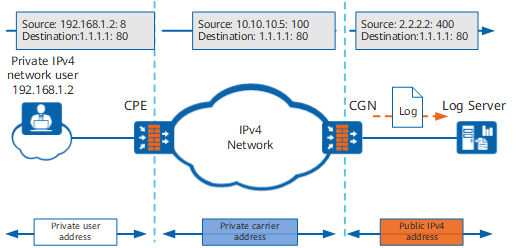
- A private IPv4 user attempts to access the IPv4 Internet and sends an IPv4 packet to the CPE.
- After receiving the IPv4 packet, the CPE translates the private address in the packet header to a private carrier address. Then the packet after NAT is forwarded to the CGN device according to the routing table.
- After receiving the packet, the CGN device translates the private carrier address to a public IPv4 address and assigns a port range to the CPE. Subsequent user traffic from the CPE to the CGN device shares these port resources. If subsequent traffic is heavy, more ports can be assigned through incremental allocation.
- By interworking with the CGN, the log server receives and analyzes the logs sent from the CGN to trace the address of the CPE.
Processing Procedure of Port Pre-Allocation and Incremental Allocation in DS-Lite
The specific processing procedure of port pre-allocation and incremental allocation in DS-Lite is shown in Figure 2.
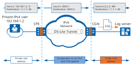
- A private IPv4 user attempts to access the IPv4 Internet and sends an IPv4 packet to the CPE.
- After receiving the private IPv4 packet, the CPE encapsulates it into an IPv4 over IPv6 packet and sends it to the CGN device over the carrier's IPv6 network.
- After receiving the packet, the CGN device translates the private user address to a public IPv4 address and assigns a port range to the CPE. Subsequent user traffic from the CPE to the CGN device shares these port resources. If subsequent traffic is heavy, more ports can be assigned through incremental allocation.
- By interworking with the CGN, the log server receives and analyzes the logs sent from the CGN to trace the address of the CPE.
Processing Procedure of Port Pre-Allocation and Incremental Allocation in NAT64
Figure 3 shows the specific processing procedure of port pre-allocation and incremental allocation in NAT64.
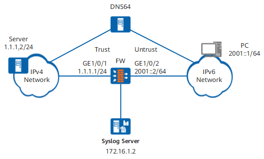
- A single-stack IPv6 user initiates an AAAA DNS request for remote services (www.admin.com).
- After receiving the request, DNS64 parses it. If an IPv6 address cannot be found, the user sends an A request. DNS64 parses the request and finds an IPv4 address. Based on the configured prefix 64::/n (64:ff9b::/96), DNS64 sends the NAT64 address (64:ff9b::0101:0102) to the user. The address resolution is complete.
- After receiving the DNS64 reply, the user sends the parsed address as a destination address to the remote server.
- After receiving the IPv6 packet from the user, the FW uses an address conversion algorithm to extract the IP address (1.1.1.2) from the IPv6 packet and uses the IPv4 address as the destination address of the IPv4 packet. After the IPv6 packet matches the port pre-allocation NAT policy, a port range is pre-allocated to the IPv6 user. If the pre-allocated port range cannot meet the service requirement, you can allocate another port range incrementally. NAT64 can create IPv6 and IPv4 sessions and convert the IPv6 packet into an IPv4 packet based on conversion information, and send the IPv4 packet to a server on an IPv4 network. After receiving the packet, the server replies to the packet.
- The FW interworks with a log server. The log server receives logs from the FW, and analyzes and parses the log information for IPv6 user tracing.
- After receiving the reply packet from the IPv4 server, the FW converts the IPv4 packet into an IPv6 packet according to the session table, and sends the IPv6 packet to the IPv6 user.