Overview of Static Mapping
This section describes the concepts and principles of static mapping.
Static mapping applies to NAT444 networks. By configuring the mapping among the private IP address pool, public IP address pool, and port range, you can improve the source tracing efficiency.
In most cases, static mapping is configured on the NMS server. The NMS server generates and maintains a static mapping table and delivers the static mapping to the CGN and AAA server, so that they can perform such operations as NAT and authentication based on the mapping.
If the NMS fails to deliver commands, you can run commands on the CGN to configure static mapping and adjust the configurations. This chapter focuses on the configuration of this static mapping.

Static mapping is a rapid NAT algorithm proposed by China Telecom. Based on the collected address mapping information, including the private IP address pool, public IP address pool, and port range allocated for public addresses, the NMS generates mappings using the algorithm, therefore implementing rapid NAT and sourcing user addresses.
There are multiple static mapping relationships, as shown in Figure 1, Figure 2, and Figure 3. The private addresses, public addresses, and number of ports are only used as examples. The actual number and proportion depend on the actual networking. On a device, address sections in an address pool are sorted in ascending order. Addresses in an address section are sorted in ascending order. Ports in a port range are sorted in ascending order.
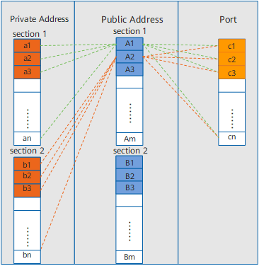
- N addresses in private address section 1 correspond to the first address in public address section 1 and the port range corresponding to the public address.
- N addresses in private address section 2 correspond to the second address in public address section 1 and the port range corresponding to the public address.
- Subsequent addresses follow the same mapping rule. If addresses in public address section 1 are used up, public address section 2 is used.
Private address a1 maps with public address A1 + port range c1
Private address a2 maps with public address A1 + port range c2
.........
Private address an maps with public address A1 + port range cn
Private address b1 maps with public address A2 + port range c1
Private address b2 maps with public address A2 + port range c2
.........
Private address bn maps with public address A2 + port range cn
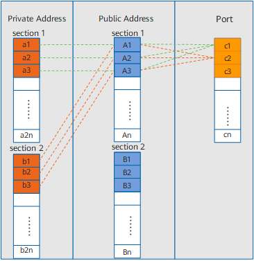
- The first n addresses in private address section 1 correspond to n addresses in public address section 1 and the smallest port range corresponding to the public addresses. If addresses in public address section 1 are used up, public address section 2 is used.
- The second n addresses in private address section 1 correspond to n addresses in public address section 2 and the smallest port range corresponding to the public addresses.
- The first n addresses in private address section 2 correspond to n addresses in public address section 1 and the second smallest port range corresponding to the public addresses. If addresses in public address section 1 are used up, public address section 2 is used.
- The second n addresses in private address section 2 correspond to n addresses in public address section 2 and the second smallest port range corresponding to the public addresses.
- Subsequent addresses follow the same mapping rule.
Private address a1 maps with public address A1 + port range c1
Private address a2 maps with public address A2 + port range c1
.........
Private address an maps with public address An + port range c1
Private address an+1 maps with public address B1 + port range c1
Private address an+2 maps with public address B2 + port range c1
.........
Private address a2n maps with public address Bn + port range c1
Private address b1 maps with public address A1 + port range c2
Private address b2 maps with public address A2 + port range c2
.........
Private address bn maps with public address An + port range c2
Private address bn+1 maps with public address B1 + port range c2
Private address bn+2 maps with public address B2 + port range c2
.........
Private address b2n maps with public address Bn + port range c2
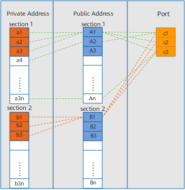
- The smallest three addresses in private address section 1 correspond to the first address in public address section 1 and the port range corresponding to the public address.
- The second smallest three addresses in private address section 1 correspond to the second address in public address section 1 and the port range corresponding to the public address.
- Subsequent addresses follow the same mapping rule.
Private address a1 maps with public address A1 + port range c1
Private address a2 maps with public address A1 + port range c2
Private address a3 maps with public address A1 + port range c3
.........
Private address a3n-2 maps with public address An + port range c1
Private address a3n-1 maps with public address An + port range c2
Private address a3n maps with public address An + port range c3
Private address b1 maps with public address B1 + port range c1
Private address b2 maps with public address B1 + port range c2
Private address b3 maps with public address B1 + port range c3
.........
Private address b3n-2 maps with public address Bn + port range cn
Private address b3n-1 maps with public address Bn + port range cn
Private address b3n maps with public address Bn + port range cn
Figure 4 shows the implementation process of static mapping.
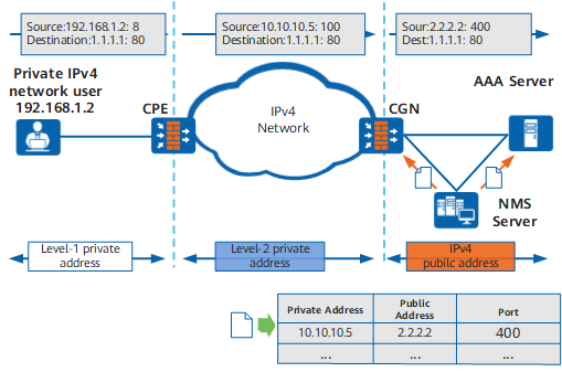
- The NMS server collects static mapping elements (including private addresses, public addresses, and port range), generates a static mapping table, and delivers the mapping to the CGN and AAA server.
- When a private IPv4 network user attempts to access the IPv4 Internet, an IPv4 packet is sent to the CPE.
- After receiving the IPv4 packet, the CPE translates the level-1 private address in the packet header into a level-2 private address and forwards the resulting packet to the CGN.
- After receiving the packet, the CGN translates the level-2 private address into a public IPv4 address based on the static mapping table and assigns the specified port range.
- The AAA server performs authentication, authorization, and accounting on the user and records and maintains information, such as the billing information and user account.