Advanced Settings
Advanced settings affect the service of the FW. You must set global parameters correctly.
Procedure
- Choose .
- Set parameters for advanced settings and click Apply.
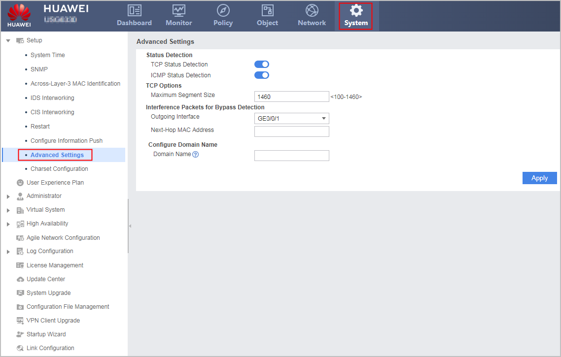
Parameter
Description
Status Detection
Enable or disable TCP Status Detection or ICMP Status Detection function.
The TCP status check function and ICMP status check function are independent of each other. Enabling or disabling of one function does not affect the status check on the other type of data flows.
NOTICE:Disabling the TCP status check function makes defending against SYN flood attacks in TCP proxy mode unavailable.
For relevant CLI configurations, see Configuring Status Check Using the CLI.
Maximum Segment Size
The default MSS is 1460 bytes.
The MSS is equal to the interface MTU deducted by 40 bytes (20-byte IP header and 20-byte TCP header). If Point-to-Point Protocol over Ethernet (PPPoE) dialup is used, additional 8 bytes (PPPoE header) must be deducted. The interface MTU deducted by 48 bytes is the MSS value.
For example:
If the interface MTU changes from 1500 bytes to 1450 bytes, the new MSS must be 1410 bytes (1450-20-20).
If the interface MTU is 1500 and PPPoE dialup is used, the MSS must be set to 1452 bytes (1500-20-20-8).
The new MSS value of TCP packets takes effect only on subsequent TCP connections, not established ones.
The TCP maximum segment size must be smaller than the link MTU. In certain scenarios, you can set the TCP maximum segment size to meet the link MTU requirement, preventing communication exceptions.
For relevant CLI configurations, see firewall tcp-mss.
Interference packets for bypass detection
When the FW is deployed in off-line mode, the function applies to the following scenarios:When the action of the security policy is allow and security policy references an antivirus or intrusion prevention profile, the function needs to be configured on the FW to block detected attacks or viruses.
NOTE:The configuration takes effect only when the attack type is a TCP attack.
When the action of the security policy is block, the function can be configured on the FW to block traffic.
NOTE:Ensure that the interference packets are returned along the original path or the path from the interface for sending interference packets to the remote client/server is reachable.
The specific configuration is as follows:If the interference packets are returned along the original path, the outbound interface of the packets does not need to be specified, and the FW sends feedback packets through the interface that receives mirrored traffic. This configuration mode applies only to Layer-2 switching.
The optical splitter cannot inject packets back. If you use an optical splitter to mirror packets to the FW, do not select return via the same interface.
If the interference packets are not returned along the original path, the outbound interface and next-hop MAC address need to be specified to send interference packets.
If the remote interface of the outbound interface of the interference packets works at Layer 2, only the outbound interface of the interference packets needs to be specified, and the next-hop MAC address does not need to be specified.
If the remote interface of the outbound interface of the interference packets works at Layer 3, the outbound interface and next-hop MAC address of the interference packets need to be specified. The next-hop MAC address is the MAC address of the remote interface.
For relevant CLI configurations, see ids-response.
Outgoing interface
Specify the interface for sending interference packets.
- Return via the same interface: Sends interference packets from the interface that the FW receives mirroring packets.
- Send via another interface: Sends interference packets from the specified interface.
The optical splitter cannot inject packets back. If you use an optical splitter to mirror packets to the FW, do not select return via the same interface.
Next-hop MAC address
Set the destination MAC address of interference packets. If you do not set this address, the source MAC address of the source packets is used as the destination MAC address of interference packets.
Domain Name
Specify the device domain name so that the user can access the device through the domain name.
The FW's domain name can replace the FW's IP address in the pushed portal page to prevent information disclosure. For example, the FW's IP address is 192.168.0.1, and the URL in the pushed portal page is http://192.168.0.1:8887/abc. After you set the device domain name to www.example.com, the URL in the portal page changes to www.example.com:8887/abc.
NOTE:- All models except USG6635E/6655E, USG6680E and USG6712E/6716E support this function.
- The mapping between the device domain name and IP address must be set on the DNS server, so that the DNS server can parse the domain name into the device's IP address.
- Currently, only the portal pages pushed by quota control policies support this function.