Implementing Load Balancing Using VRRP
If two FWs work in the load balancing mode, the two FWs must have an active VRRP group.
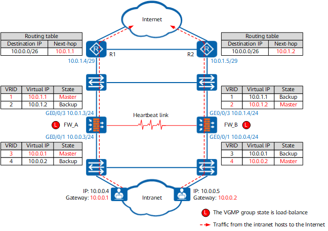
As shown in Figure 1, the state of VRRP groups 1 and 3 on FW_A is set to active, and the state of VRRP groups 2 and 4 is set to standby. The state of VRRP groups 2 and 4 of FW_B is set to active, and the state of VRRP groups 1 and 3 is set to standby. Normally, the state of the VGMP group is load-balance on the two FWs, and the state of the VRRP group is determined by the configuration. Therefore, VRRP groups 1 and 3 of FW_A are in the Master state, and VRRP groups 2 and 4 are in the Backup state. VRRP groups 2 and 4 of FW_B are in the Master state, and VRRP groups 1 and 3 are in the Backup state.
The gateway address on some intranet hosts is set to the virtual IP address (10.0.0.1) of VRRP group 3. When an intranet host accesses the Internet, it broadcasts an ARP request to request the MAC address mapped to 10.0.0.1. VRRP group 3 on FW_A is in the Master state and responds to the ARP requests from the intranet host. VRRP group 3 on FW_B is in the Backup state and does not respond to ARP requests from intranet host. The MAC address table of the switch and the ARP cache tables of the hosts are updated based on the ARP reply packets from FW_A so that the traffic sent from these hosts to the Internet is diverted to FW_A for processing.
The gateway address on other intranet hosts is set to the virtual IP address (10.0.0.2) of VRRP group 4. When an intranet host accesses the Internet, it broadcasts an ARP request to request the MAC address mapped to 10.0.0.2. In this case, only FW_B responds to the ARP request. Therefore, the traffic of these hosts is diverted to FW_B for forwarding.
Similarly, the next hop address of the route pointing to the intranet is set to the virtual IP address (10.0.1.1) of VRRP group 1 on R1 so that the traffic from R1 to the intranet is diverted to FW_A for processing. The next hop address of the route pointing to the intranet is set to the virtual IP address (10.0.1.2) of VRRP group 2 on R2 so that the traffic from R2 to the intranet is diverted to FW_B for processing.
FW_A |
FW_B |
|---|---|
# interface GigabitEthernet 0/0/1 vrrp vrid 3 virtual-ip 10.0.0.1 active vrrp vrid 4 virtual-ip 10.0.0.2 standby # interface GigabitEthernet 0/0/3 vrrp vrid 1 virtual-ip 10.0.1.1 active vrrp vrid 2 virtual-ip 10.0.1.2 standby |
# interface GigabitEthernet 0/0/1 vrrp vrid 3 virtual-ip 10.0.0.1 standby vrrp vrid 4 virtual-ip 10.0.0.2 active # interface GigabitEthernet 0/0/3 vrrp vrid 1 virtual-ip 10.0.1.1 standby vrrp vrid 2 virtual-ip 10.0.1.2 active |
As shown in Figure 2, the upstream service interface of FW_A is faulty, and the state of VRRP groups 1 and 2 of FW_A changes to Initialize. In addition, the state of VGMP groups on FW_A and FW_B also changes. The state of the VGMP group changes to standby on FW_A and to active on FW_B. FW_A and FW_B adjust the state of the VRRP group based on the VGMP group status. The state of VRRP groups 3 and 4 on FW_A changes to Backup. The state of all VRRP groups on FW_B changes to Master.
When the state of the VRRP group on FW_B changes from Backup to Master, gratuitous ARP packets are broadcast. The packets carry the virtual IP address of the VRRP group and the MAC address of the interface (the virtual MAC address if the virtual MAC address function is enabled on the interface). The MAC address table of the switch and the ARP cache tables of the hosts and router are updated based on the gratuitous ARP packets. In this way, the traffic between the intranet and Internet is diverted to FW_B for forwarding.
Similarly, if FW_B is faulty and FW_A is normal, traffic between intranet and Internet is diverted to FW_A for forwarding.
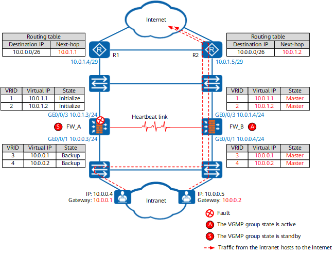
In conclusion, in normal cases, both FW_A and FW_B process traffic between the intranet and Internet. FW_A and FW_B work in load balancing mode. When either FW_A or FW_B fails, traffic is automatically switched to the normal FW to ensure service continuity.