Hot Standby in Mirroring Mode
This section describes the mechanism of hot standby in mirroring mode.
Mirroring Mode
Mirroring mode is a technical means to implement hot standby. About the mirroring mode, you need to understand the following information:
- Use two FWs in the initial state to work in mirroring mode. If the FWs have been running services, do not directly switch a non-mirroring mode to the mirroring mode. Instead, you must restore the device to the initial state and then switch it to the mirroring mode. Otherwise, services will be affected.
- When hot standby is implemented in mirroring mode, the two FWs work in active/standby mode and cannot work in load balancing mode. And mirroring mode is mainly used in DCN and cloud management scenarios.
- When hot standby is implemented in mirroring mode, service interfaces with the same ID on the two FWs use the same IP address. The service interfaces refer to the interfaces except MGMT interface, mirroring management interface, and heartbeat interface.
- When IPv6 hot standby is implemented in mirroring mode, service interfaces numbered the same on the two FWs must use the same IPv6 address and IPv6 link-local address. Please manually configure the IPv6 link-local address. Do not configure the automatically generated link-local addresses for the interfaces to avoid inconsistency.
- The mirroring mode and VRRP function are mutually exclusive. If VRRP is configured on the FWs, the mirroring mode cannot be enabled. After the mirroring mode is enabled, VRRP cannot be configured on the FWs.
- When hot standby is implemented in mirroring mode, the hrp base config enable command can be run only in DCN scenarios. This command is prohibited in other scenarios to prevent service exceptions.
- After the mirroring mode is enabled, more configurations can be backed up between the two FWs. For example, when the mirroring mode is disabled, the interface IP address configuration cannot be backed up. After the mirroring mode is enabled, the interface IP address configuration can be backed up. For details, see List of Configurations Supporting Backup and Not Supporting Backup.
- After the mirroring mode is enabled, the FW can adjust the status of the service interface according to the VGMP group status.
- When the status of a VGMP group is load-balance, the status of the service interface is determined by the configuration. If the hrp standby-device command is configured on a FW to specify the FW as the standby FW, the service interfaces are changed to passive state.
- When the VGMP group is in the active state, the service interfaces are changed to the non-passive state, and the service interface can send and receive packets normally.
- When the VGMP group is in the standby state, the service interfaces are changed to the passive state. Then, the service interfaces do not receive or send packets (such as ARP and routing protocol packets) except LLDP and LACP packets. Because of this, the following functions are not supported in mirroring mode:
The FW does not support monitoring of remote interface faults through BFD/IP-Link.
Using BFD as an example, the standby FW in mirroring mode does not send BFD detection packets; therefore, the BFD status of the standby FW is always Down. If hot standby is associated with BFD, the priority of the VGMP group on the standby FW decreases by 2. Therefore, if the BFD status or an interface of the active FW becomes Down, the active/standby switchover does not take place.
Only static routes are supported between the FW and its upstream and downstream devices. Dynamic routes and intelligent uplink selection are not supported. The FW does not support monitoring of remote neighbor faults through OSPF and BGP.
Using dynamic routes as an example, in mirroring mode, the standby FW does not send or receive route negotiation packets. Therefore, neighbor relationships with upstream and downstream devices in dynamic routing cannot be set up on the standby FW. During the active/standby switchover, the new active FW needs to renegotiate routes with upstream and downstream devices. Services are interrupted for a long period during the active/standby switchover.
Traffic Forwarding and Failover Mechanism in Mirroring Mode
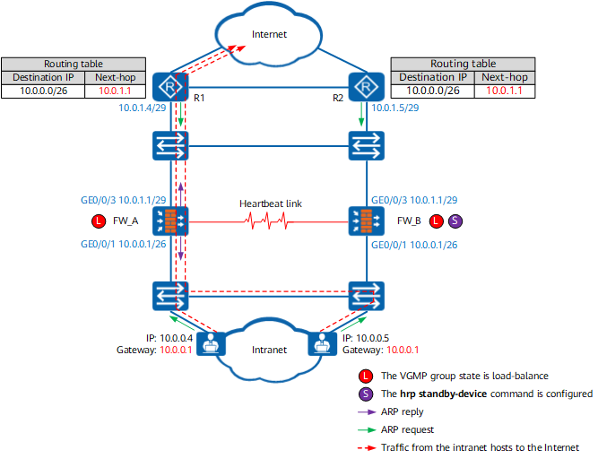
As shown in Figure 1, FW_A and FW_B work in mirroring mode. The two FWs use the same upstream and downstream service interface addresses. To enable the two FWs to work in active/standby mode, run the hrp standby-device command on one FW to specify the FW as the standby FW.
Because the gateway is set to the IP address (10.0.0.1) of the downstream service interface on the hosts on the intranet, these hosts broadcast an ARP request packet when accessing the Internet to request the MAC address of 10.0.0.1. FW_A responds to the ARP requests from the intranet host. FW_B does not respond to ARP requests from intranet hosts because the hrp standby-device is configured. The MAC address table of the switch and the ARP cache tables of the hosts are updated based on the ARP reply packets from FW_A so that the traffic sent from the hosts to the Internet is diverted to FW_A for processing.
Similarly, the next hop address of the route pointing to the intranet is set to the IP address (10.0.1.1) of the upstream interface on R1 and R2. The traffic sent from the Internet to the intranet is also diverted to FW_A for processing.
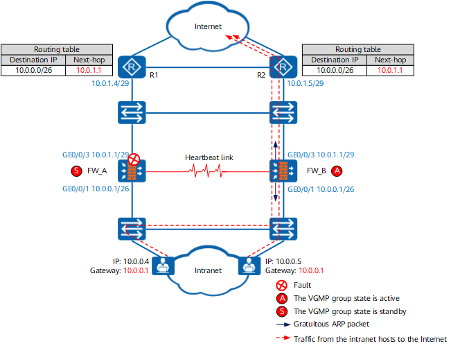
As shown in Figure 2, the upstream service interface of FW_A is faulty. The state of the VGMP group changes to standby on FW_A and to active on FW_B. When the status of the VGMP group on FW_B changes to active, the service interfaces send gratuitous ARP packets. The MAC address table of the switches and the ARP cache tables of the hosts and routers are updated based on the gratuitous ARP packets. In this way, the traffic between the intranet and Internet is diverted to FW_B for forwarding. When the two FWs receive ARP request packets or service packets, only FW_B responds to the ARP request or forwards service packets, and FW_A discards the packets.
Mirroring Mode Management Interface
By default, only the MGMT interface and the heartbeat interface of the standby device can receive or send packets. However, in some scenarios, the standby device needs to receive and send packets. For example, the standby device needs to send logs to the log server or communicate with the NMS server. In this case, you can run the hrp mgt-interface command on the standby device to specify the mirroring mode management interfaces to send logs and communicate with the NMS server.
The following types of interfaces can be configured as management interfaces in mirroring mode:
- Layer 3 Ethernet interface
- Layer-3 Eth-Trunk interface
- VLANIF interface
In mirroring mode, management, heartbeat, and service interfaces are dedicated to their own purposes. That is, after an interface is configured as a management interface in mirroring mode, the interface and its subinterfaces cannot be used as heartbeat or service interfaces.