Web: Example for Deploying Firewalls in In-path Mode and Connecting to Routers Through OSPF in the Upstream Direction and Switches in the Downstream Direction
This section provides a web example of configuring hot standby in load balancing mode in which the service interfaces of the firewalls work at Layer 3 and connect to routers through OSPF in the upstream direction and switches in the downstream direction.
Networking Requirements
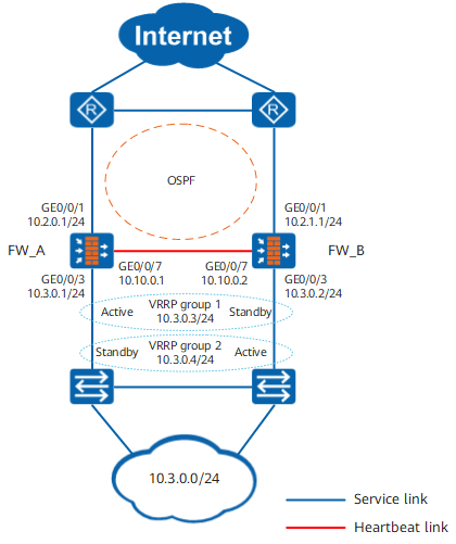
On the network shown in Figure 1, the service interfaces of two FWs work at Layer 3, with routers as upstream devices and switches as downstream devices. The FWs and directly connected routers run OSPF.
The FWs are expected to work in load balancing mode. Normally, both FW_A and FW_B forward traffic. When one FW goes faulty, the other FW takes over all the traffic load.
Procedure
- Configure interfaces and basic network configurations.
- Configure OSPF to ensure IP connectivity.
- Configure OSPF on FW_A.
- Choose .

- Click Add, create an OSPF process and set the parameters as follows, and then click OK.
Type
OSPFv2
Process ID
10
- Click
 , click Add, create an OSPF area and set the parameters as follows, and click OK.
Area
0.0.0.0
IP Network
10.2.0.0
Mask/Wildcard Mask
255.255.255.0
- Choose , click Add, create a network and set the parameters as follows, and then click OK.
Area
0.0.0.0
IP Network
10.3.0.0
Mask/Wildcard Mask
255.255.255.0
- Choose .
- Configure OSPF on FW_B.
- Click Add, create an OSPF process and set the parameters as follows, and then click OK.
Type
OSPFv2
Process ID
10
- Click , click Add, create an OSPF area and set the parameters as follows, and click OK.
Area
0.0.0.0
IP Network
10.2.1.0
Mask/Wildcard Mask
255.255.255.0
- Choose , click Add, create a network and set the parameters as follows, and then click OK.
Area
0.0.0.0
IP Network
10.3.0.0
Mask/Wildcard Mask
255.255.255.0
- Click Add, create an OSPF process and set the parameters as follows, and then click OK.
- Configure OSPF on FW_A.
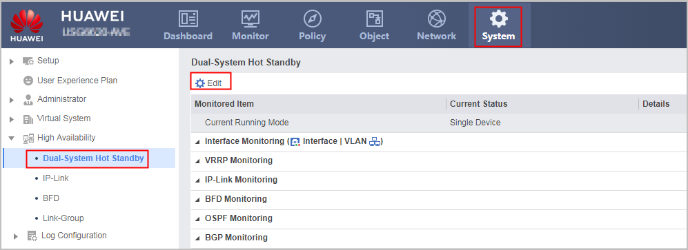
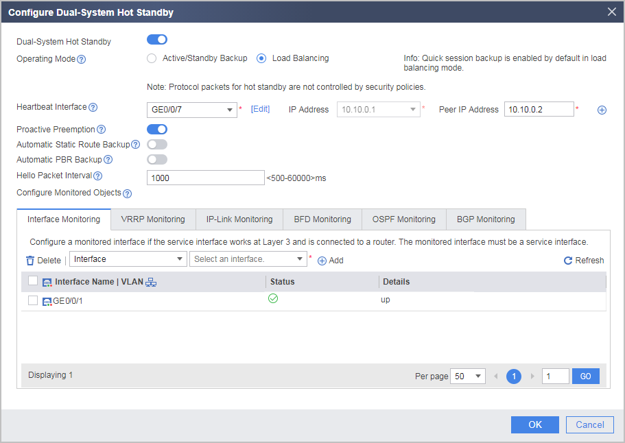
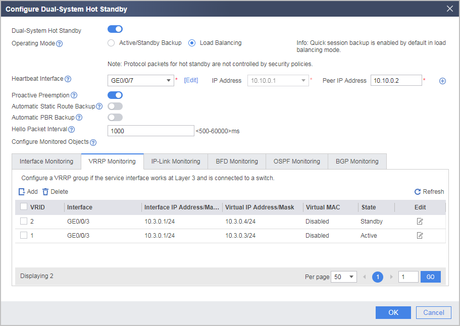
- Configure hot standby.
- Configure the default routes on intranet devices. You can set the next hop of some devices to the virtual IP address (10.3.0.3) of VRRP group 1 and that of other devices to the virtual IP address (10.3.0.4) of VRRP group 2.
- Configure the security policies.
Security policies configured on FW_A are automatically backed up to FW_B.
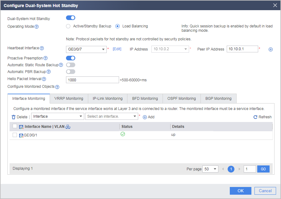
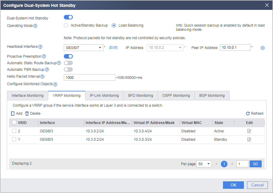
Configuration Verification
Choose to view the operating status of hot standby.
- Normally, the Current Running Mode of FW_A is Load Balancing and the Current Status is Active. The Current Running Mode of FW_B is Load Balancing and the Current Status is Active. This shows that traffic is forwarded by FW_A.
- When FW_A goes faulty, the Current Running Mode of FW_A is Active/Standby Backup and the Current Status is Standby. The Current Running Mode of FW_B is Active/Standby Backup and the Current Status is Active. This shows that traffic is forwarded by FW_B.
Configuration Scripts
FW_A |
FW_B |
|---|---|
# hrp enable hrp interface GigabitEthernet 0/0/7 remote 10.10.0.2 hrp mirror session enable hrp track interface GigabitEthernet 0/0/1 # interface GigabitEthernet 0/0/1 ip address 10.2.0.1 255.255.255.0 # interface GigabitEthernet 0/0/3 ip address 10.3.0.1 255.255.255.0 vrrp vrid 1 virtual-ip 10.3.0.3 active vrrp vrid 2 virtual-ip 10.3.0.4 standby # interface GigabitEthernet 0/0/7 ip address 10.10.0.1 255.255.255.0 # firewall zone trust set priority 85 add interface GigabitEthernet 0/0/3 # firewall zone untrust set priority 5 add interface GigabitEthernet 0/0/1 # firewall zone dmz set priority 50 add interface GigabitEthernet 0/0/7 # ospf 10 area 0.0.0.0 network 10.2.0.0 0.0.0.255 network 10.3.0.0 0.0.0.255 # security-policy rule name policy_ospf_1 source-zone local destination-zone untrust action permit rule name policy_ospf_2 source-zone untrust destination-zone local action permit rule name policy_sec source-zone trust destination-zone untrust source-address 10.3.0.0 24 action permit |
# hrp enable hrp interface GigabitEthernet 0/0/7 remote 10.10.0.1 hrp mirror session enable hrp track interface GigabitEthernet 0/0/1 # interface GigabitEthernet 0/0/1 ip address 10.2.1.1 255.255.255.0 # interface GigabitEthernet 0/0/3 ip address 10.3.0.2 255.255.255.0 vrrp vrid 1 virtual-ip 10.3.0.3 standby vrrp vrid 2 virtual-ip 10.3.0.4 active # interface GigabitEthernet 0/0/7 ip address 10.10.0.2 255.255.255.0 # firewall zone trust set priority 85 add interface GigabitEthernet 0/0/3 # firewall zone untrust set priority 5 add interface GigabitEthernet 0/0/1 # firewall zone dmz set priority 50 add interface GigabitEthernet 0/0/7 # ospf 10 area 0.0.0.0 network 10.2.1.0 0.0.0.255 network 10.3.0.0 0.0.0.255 # security-policy rule name policy_ospf_1 source-zone local destination-zone untrust action permit rule name policy_ospf_2 source-zone untrust destination-zone local action permit rule name policy_sec source-zone trust destination-zone untrust source-address 10.3.0.0 24 action permit |