CLI: Example for Configuring Interworking Between Hot Standby and BFD
Introduce the example for configuring interworking between BFD and hot standby according to the example for configuring active/standby mode.
Network Requirements
The FW is deployed on the service node as a security device. Upstream and downstream devices are routers. FW_A and FW_B work in active/standby mode
Figure 1 shows the networking diagram. The detailed description is as follows:
- OSPF is applied among the router and two FWs. The router sends service packets to the Active FW according to the route calculation result.
- FW monitor the network egress through the interworking function between BFD and hot standby. When the network egress on the link where FW_A resides is down, FW_B can switch to active device and the service packets are sent to FW_B.
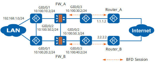
Procedure
- Configure the hot standby function on FW_A.
# Set an IP address for GigabitEthernet 0/0/1.
<FW_A> system-view
[FW_A] interface GigabitEthernet 0/0/1
[FW_A-GigabitEthernet0/0/1] ip address 10.100.10.2 24
[FW_A-GigabitEthernet0/0/1] quit
# Add GigabitEthernet 0/0/1 to the Trust zone.
[FW_A] firewall zone trust
[FW_A-zone-trust] add interface GigabitEthernet 0/0/1
[FW_A-zone-trust] quit
# Set an IP address for GigabitEthernet 0/0/3.
[FW_A] interface GigabitEthernet 0/0/3
[FW_A-GigabitEthernet0/0/3] ip address 10.100.30.2 24
[FW_A-GigabitEthernet0/0/3] quit
# Add GigabitEthernet 0/0/3 to the Untrust zone.
[FW_A] firewall zone untrust
[FW_A-zone-untrust] add interface GigabitEthernet 0/0/3
[FW_A-zone-untrust] quit
# Set an IP address for GigabitEthernet 0/0/2.
[FW_A] interface GigabitEthernet 0/0/2
[FW_A-GigabitEthernet0/0/2] ip address 10.100.50.2 24
[FW_A-GigabitEthernet0/0/2] quit
# Add GigabitEthernet 0/0/2 to the DMZ zone.
[FW_A] firewall zone dmz
[FW_A-zone-dmz] add interface GigabitEthernet 0/0/2
[FW_A-zone-dmz] quit
# Run the OSPF dynamic routing protocol on FW_A.
[FW_A] ospf 101
[FW_A-ospf-101] area 0
[FW_A-ospf-101-area-0.0.0.0] network 10.100.10.0 0.0.0.255
[FW_A-ospf-101-area-0.0.0.0] network 10.100.30.0 0.0.0.255
[FW_A-ospf-101-area-0.0.0.0] quit
[FW_A-ospf-101] quit
# Enable the function of adjusting the related cost value of OSPF according to the HRP status.
[FW_A] hrp adjust ospf-cost enable# Configure the VGMP group to monitor the status of interfaces.
[FW_A] hrp track interface GigabitEthernet 0/0/1
[FW_A] hrp track interface GigabitEthernet 0/0/3
# Configure an HRP backup channel.
[FW_A] hrp interface GigabitEthernet 0/0/2 remote 10.100.50.3
# Enable HRP.
[FW_A] hrp enable - Configure the hot standby function on FW_B.
The configuration on the FW_B is similar to that on the FW_A. The differences are as follows:
- The IP addresses of interfaces on FW_B should be different from those of interfaces on FW_A; moreover, the IP addresses of the service interfaces corresponding to FW_B and FW_A should not be on the same network segment.
- When OSPF is executed on FW_B, the route to the network segment directly connected to the service interface on FW_B should be advertised.
- Run the hrp standby-device command on FW_B to specify FW_B as a standby device.
- Configure IP addresses and OSPF on the router to ensure the network is reachable. For detailed configuration commands, refer to documents related to the router.
- Configure security policies.
The security policy configured on FW_A are automatically backed up to FW_B.
# Configure security policy to ensure that the users on network segment 192.168.1.0/24 can access the Untrust zone.
HRP_M[FW_A] security-policy
HRP_M[FW_A-policy-security] rule name policy1
HRP_M[FW_A-policy-security-rule-policy1] source-zone trust
HRP_M[FW_A-policy-security-rule-policy1] destination-zone untrust
HRP_M[FW_A-policy-security-rule-policy1] source-address 192.168.1.0 24
HRP_M[FW_A-policy-security-rule-policy1] action permit
HRP_M[FW_A-policy-security-rule-policy1] quit
# Configure security policies between the Local zone and the security zone where GE 1/0/3 resides to permit BFD packets.
HRP_M[FW_A-policy-security] rule name bfd1
HRP_M[FW_A-policy-security-rule-bfd1] source-zone local
HRP_M[FW_A-policy-security-rule-bfd1] destination-zone untrust
HRP_M[FW_A-policy-security-rule-bfd1] source-address 10.100.30.2 32
HRP_M[FW_A-policy-security-rule-bfd1] source-address 10.100.40.2 32
HRP_M[FW_A-policy-security-rule-bfd1] destination-address 1.1.1.2 32
HRP_M[FW_A-policy-security-rule-bfd1] destination-address 2.2.2.2 32
HRP_M[FW_A-policy-security-rule-bfd1] action permit
HRP_M[FW_A-policy-security-rule-bfd1] quit
HRP_M[FW_A-policy-security] rule name bfd2
HRP_M[FW_A-policy-security-rule-bfd2] source-zone untrust
HRP_M[FW_A-policy-security-rule-bfd2] destination-zone local
HRP_M[FW_A-policy-security-rule-bfd2] source-address 1.1.1.2 32
HRP_M[FW_A-policy-security-rule-bfd2] source-address 2.2.2.2 32
HRP_M[FW_A-policy-security-rule-bfd2] destination-address 10.100.30.2 32
HRP_M[FW_A-policy-security-rule-bfd2] destination-address 10.100.40.2 32
HRP_M[FW_A-policy-security-rule-bfd2] action permit
HRP_M[FW_A-policy-security-rule-bfd2] quit
- Configure BFD sessions on FW_A and Router_A.
# Configure BFD session 1 with peer IP address 1.1.1.2, local discriminator 10, and remote discriminator 20 on FW_A.
HRP_M[FW_A] bfd
HRP_M[FW_A-bfd] quit
HRP_M[FW_A] bfd 1 bind peer-ip 1.1.1.2
HRP_M[FW_A-bfd-session-1] discriminator local 10
HRP_M[FW_A-bfd-session-1] discriminator remote 20
HRP_M[FW_A-bfd-session-1] commit
HRP_M[FW_A-bfd-session-1] quit
# Configure BFD session 1 with peer IP address 10.100.30.2, local discriminator 20, and remote discriminator 10 on Router_A.
<Router_A> system-view
[Router_A] bfd
[Router_A-bfd] quit
[Router_A] bfd 1 bind peer-ip 10.100.30.2
[Router_A-bfd-session-1] discriminator local 20
[Router_A-bfd-session-1] discriminator remote 10
[Router_A-bfd-session-1] commit
[Router_A-bfd-session-1] quit
- Configure interworking between BFD and hot standby on FW_A.
HRP_M[FW_A] hrp track bfd-session 10 - Configure BFD sessions on FW_B and Router_B.
# Configure BFD session 1 with peer IP address 2.2.2.2, local discriminator 10, and remote discriminator 20 on FW_B.
HRP_S[FW_B] bfd
HRP_S[FW_B-bfd] quit
HRP_S[FW_B] bfd 1 bind peer-ip 2.2.2.2
HRP_S[FW_B-bfd-session-1] discriminator local 10
HRP_S[FW_B-bfd-session-1] discriminator remote 20
HRP_S[FW_B-bfd-session-1] commit
HRP_S[FW_B-bfd-session-1] quit
# Configure BFD session 1 with peer IP address 10.100.40.2, local discriminator 20, and remote discriminator 10 on Router_B.
<Router_B> system-view
[Router_B] bfd
[Router_B-bfd] quit
[Router_B] bfd 1 bind peer-ip 10.100.40.2
[Router_B-bfd-session-1] discriminator local 20
[Router_B-bfd-session-1] discriminator remote 10
[Router_B-bfd-session-1] commit
[Router_B-bfd-session-1] quit
- Configure interworking between BFD and hot standby on FW_B.
HRP_S[FW_B] hrp track bfd-session 10
Configuration Script
FW_A |
FW_B |
|---|---|
# sysname FW_A # bfd # hrp enable hrp interface GigabitEthernet 0/0/2 remote 10.100.50.3 hrp track interface GigabitEthernet 0/0/1 hrp track interface GigabitEthernet 0/0/3 hrp track bfd-session 10 # interface GigabitEthernet 0/0/1 ip address 10.100.10.2 255.255.255.0 # interface GigabitEthernet 0/0/2 ip address 10.100.50.2 255.255.255.0 # interface GigabitEthernet 0/0/3 ip address 10.100.30.2 255.255.255.0 # firewall zone trust add interface GigabitEthernet 0/0/1 # firewall zone dmz add interface GigabitEthernet 0/0/2 # firewall zone untrust add interface GigabitEthernet 0/0/3 # bfd 1 bind peer-ip 1.1.1.2 discriminator local 10 discriminator remote 20 commit # ospf 101 area 0.0.0.0 network 10.100.10.0 0.0.0.255 network 10.100.30.0 0.0.0.255 # security-policy rule name policy1 source-zone trust destination-zone untrust source-address 192.168.1.0 24 action permit rule name bfd1 source-zone local destination-zone untrust source-address 10.100.30.2 32 source-address 10.100.40.2 32 destination-address 1.1.1.2 32 destination-address 2.2.2.2 32 action permit rule name bfd2 source-zone untrust destination-zone local source-address 1.1.1.2 32 source-address 2.2.2.2 32 destination-address 10.100.30.2 32 destination-address 10.100.40.2 32 action permit # return |
# sysname FW_B # bfd # hrp enable hrp standby-device hrp interface GigabitEthernet 0/0/2 remote 10.100.50.2 hrp track interface GigabitEthernet 0/0/1 hrp track interface GigabitEthernet 0/0/3 hrp track bfd-session 10 # interface GigabitEthernet 0/0/1 ip address 10.100.20.2 255.255.255.0 # interface GigabitEthernet 0/0/2 ip address 10.100.50.3 255.255.255.0 # interface GigabitEthernet 0/0/3 ip address 10.100.40.2 255.255.255.0 # firewall zone trust add interface GigabitEthernet 0/0/1 # firewall zone dmz add interface GigabitEthernet 0/0/2 # firewall zone untrust add interface GigabitEthernet 0/0/3 # bfd 1 bind peer-ip 2.2.2.2 discriminator local 10 discriminator remote 20 commit # ospf 101 area 0.0.0.0 network 10.100.20.0 0.0.0.255 network 10.100.40.0 0.0.0.255 # security-policy rule name ha source-zone trust destination-zone untrust source-address 192.168.1.0 24 action permit rule name bfd1 source-zone local destination-zone untrust source-address 10.100.30.2 32 source-address 10.100.40.2 32 destination-address 1.1.1.2 32 destination-address 2.2.2.2 32 action permit rule name bfd2 source-zone untrust destination-zone local source-address 1.1.1.2 32 source-address 2.2.2.2 32 destination-address 10.100.30.2 32 destination-address 10.100.40.2 32 action permit # return |