Understanding Global Route Selection Policy
This section describes the overview of the global route selection policy, intelligent uplink selection mode, and the sticky session function.
Overview
In a multi-egress scenario, when there are multiple equal-cost routes or default routes to the destination network, the FW forwards traffic in per-flow load balancing mode by default, and uses hash calculation to select the outbound interface based on source and destination IP addresses. That is, the source and destination IP addresses of a packet determine the route regardless of the actual bandwidth or real-time status of each link. If the traffic volume is large, some links may be congested, and the others may be idle, which causes a waste of link resources. When a link has poor transmission quality, Internet access may fail, which compromises user experience. The user cannot select specific link to forward the traffic. Therefore, there might be extra charges.
The global route selection policy can solve the preceding problems. When there are multiple equal-cost routes or default routes to the destination network, the global route selection policy enables the device to select an outbound interface based on the intelligent uplink selection mode, that is, link bandwidth, weight, priority, or automatically detected link quality, and dynamically adjust the selection result based on the real-time status of each link. In this way, link resources can be properly used and user experience is improved.
Intelligent Uplink Selection Mode
The FW supports four intelligent uplink selection modes. You can configure different intelligent uplink selection modes according to your situations.

Unless otherwise specified, the concepts of "interface" and "interface link" are the same when you configure the intelligent uplink selection mode. You need to configure link bandwidths, weights, and priorities of interfaces on the FW.
Mode |
Definition |
Deployment |
Application Scenario |
|---|---|---|---|
Load Balancing by Link Bandwidth |
FW forwards traffic to each link based on the bandwidth ratio. Therefore, the link with larger bandwidth forwards more traffic, the link with less bandwidth forwards less traffic, but the efficiencies of all links are maximized. |
Configure bandwidths for both incoming and outgoing traffic on the outbound interface of each link. The administrator needs to set a proper bandwidth for each link based on the actual link bandwidth. |
When an enterprise obtains links with different bandwidths from different ISPs, set the link selection mode to load balancing by link bandwidth to maximize the efficiency of link bandwidths. For details, see Load Balancing by Link Bandwidth. |
Load Balancing by Link Quality |
The FW preferentially uses the link with the best quality to forward traffic. |
Set parameters for measuring the link quality, including packet loss ratio, delay, and jitter. You can set one or more parameters as required. For details about how to calculate the three parameters, see Load Balancing by Link Quality. Among the three parameters, the packet loss ratio is the most important. If the packet loss ratio, delay, and jitter of two links are different, the FW considers the link with a smaller packet loss ratio as the higher quality link. |
If an enterprise has multiple ISP links and the FW needs to dynamically adjust traffic forwarding based on real-time traffic transmission quality of the link, you can set the link selection mode to load balancing by link quality. For details, see Load Balancing by Link Quality. |
Load Balancing by Link Weight |
FW forwards traffic to each link based on the weight ratio. Therefore, the link with the larger weight forwards more traffic, and the link with the smaller weight forwards less traffic, but all links are used in a manner to maximize link efficiency. |
Configure the weight on the outbound interface of each link. Generally speaking, when you set weight for interfaces on the FW, you need to consider factors, such as link bandwidth, forwarding delay, and link rent. The "link with the best performance" does not mean the link with the fastest forwarding speed, but the link that best meets enterprise interests. Therefore, you need to set a proper weight for each link based on the actual conditions. |
If an enterprise has ISP links with different performances, you can select the link with the best performance to ensure the experience of most users and maximize the efficiency of other links. In such scenarios, you can set the link selection mode to load balancing by link weight. For details, see Load Balancing by Link Weight. |
Active/Standby Backup by Link Priority |
FW uses the active interface preferentially to forward traffic. |
You set a proper priority for each interface, the interface with the highest priority is the active interface, and all the other interfaces are standby interfaces. The intelligent uplink selection mode can be applied to active/standby backup and load balancing scenarios. For details, see Active/Standby Backup by Link Priority. |
If an enterprise has multiple ISP links with differentiated bandwidths, forwarding delays, and link rents, you can preferentially use some link to transmit traffic and other links as backup links or load balancing links to improve availability. In such scenarios, you can set the link selection mode to active/standby backup by link priority. For details, see Active/Standby Backup by Link Priority. |
Load Balancing by Link Bandwidth
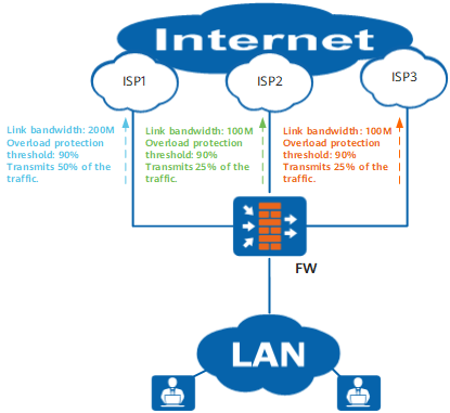
As shown in Figure 1, the FW has three different ISP links. The bandwidth for ISP1 link is 200 Mbit/s, and those for ISP2 and ISP3 are both 100 Mbit/s. Therefore, the bandwidth ratio is 2:1:1. After the FW has forwarded traffic for a while, the traffic statistics show that the history traffic of each link accounts for 50%, 25%, and 25% of the total traffic. That is, the ratio of traffic on each link is in proportion with the bandwidth ratio.
The FW distributes traffic based on the bandwidth ratio of each interface, but not the real-time traffic rate. Therefore, it is difficult to ensure that the proportion of traffic distributed to each interface is consistent with the configured bandwidth ratio.
For example, if the bandwidth ratio of three existing links is set to 2:1:1 and there are four flows. The FW will distribute the four flows to the three links according to bandwidth ratio 2:1:1. Specifically, two flows are distributed to link 1, one flow is distributed to link 2, and one flow is distributed to link 3. However, the traffic rates of the flows are different. As a result, the proportion of traffic forwarded by the traffic is not 2:1:1 actually.
To ensure that the links are not overloaded, you can set an overload protection threshold for each link (90% for all links). If the bandwidth utilization of a link reaches 90%, traffic for existing sessions is still forwarded over the link, and traffic for new sessions will not be forwarded over the link. The FW will implement load balancing based on the bandwidth ratio of unloaded links for traffic of new sessions. When all links are overloaded, the FW continues to forward traffic based on the bandwidth ratio of all links.
Load Balancing by Link Quality
Packet loss ratio, delay, and jitter are three parameters for the FW to evaluate link quality. Table 2 lists the methods for calculating each link quality parameter.
Link Quality Parameter |
Calculation Method |
|---|---|
Packet loss ratio |
After sending multiple probe packets, the FW counts the number of dropped packets and calculates the packet loss ratio. The packet loss ratio is the number of dropped packets divided by the number of probe packets. |
Delay |
Subtracting the probe sending time from the reply receiving time is the delay. The average delay of the N probe packets sent by the FW is the final delay. |
Jitter |
The absolute value of the difference between two adjacent probe delays is jitter. The average jitter of the N probe packets sent by the FW is the final jitter. |
The FW automatically sends link quality probe packets to the destination IP address, obtains the transmission quality information of each link, and saves the link quality probe result in the link quality probe table. After receiving traffic, the FW searches the probe table based on the destination IP address of the packet. If the match is found, the traffic is forwarded through the outbound interface recorded in the probe table. If not, the system automatically sends a quality probe packet to the destination IP address, selects the optimal link for traffic forwarding, and records the probe result in the link quality probe table. When a link quality probe entry ages and new traffic triggers intelligent uplink selection, the link quality needs to be detected again.
The default protocol type of link quality detection packets is tcp-simple (the FW uses TCP packets to check link connectivity. If the destination address responds to the first probe packet, the link is available, and the three-way handshake is not required). The FW uses tcp-simple to implement quality detection for TCP service traffic and ICMP to implement quality detection for non-TCP service traffic. You can change the protocol type to ICMP. Then the FW will use ICMP to implement quality detection for all service traffic.
To simplify the configuration and relieve the probing impacts on device performance, the FW uses the probe result of a specific IP address on a subnet as the result for the subnet. You can determine the size of the subnet as required.
If an overload protection threshold is set for each link and the link with the highest quality is overloaded, the link is excluded from intelligent uplink selection, and the FW will select the link with the second highest quality to forward the traffic. If all links are overloaded, the FW will distribute traffic by link bandwidth ratio.
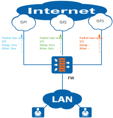
As shown in Figure 2, the FW has three different ISP links. The FW sends five probe packets to the specified device on each ISP network. No packet is dropped on ISP1 link, two packets are dropped on ISP2 link, and ISP3 link does not have any reply packets. Therefore, the FW determines that the ISP1 link has the highest quality and uses ISP1 link preferentially to forward traffic, until the probe entry is not aged out. If you set an overload protection threshold for each link and the bandwidth usage of ISP1 link reaches the threshold, ISP1 link is excluded from intelligent uplink selection, and the FW will use the link with the second highest quality (ISP2 link) to forward subsequent traffic.
Load Balancing by Link Weight
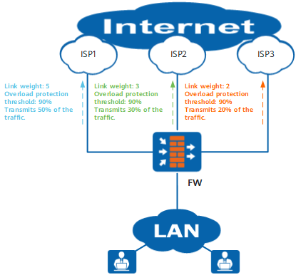
As shown in Figure 3, the FW has three different ISP links. The weights of ISP1, ISP2, and ISP3 links are respectively 5, 3, and 2. The weight ratio is 5:3:2. After the FW has forwarded traffic for a while, the traffic statistics show that the history traffic of each link accounts for 50%, 30%, and 20% of the total traffic. That is, the ratio of traffic on each link is in proportion with the weight ratio.
To ensure that the links are not overloaded, you can set an overload protection threshold for each link (90% for all links). When the bandwidth usage of a link reaches 90%, the FW no longer forwards traffic to this link and implements load balancing based on the weight ratio of the links that are not overloaded. When all links are overloaded, the FW continues to forward traffic based on the weight ratio of all links.
Active/Standby Backup by Link Priority
The intelligent uplink selection mode is applied to the following scenarios:
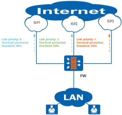
- active/standby backup: FW uses the active interface preferentially to forward traffic. If no overload protection threshold is specified for the active interface, the FW will not use other links to transmit traffic even if the link is overloaded. The standby interface with the second highest priority is activated to substitute the active interface only after the link of the active interface fails. Other backup interfaces remain backup.
- load balancing: To improve transmission reliability, you can set an overload protection threshold for each interface. When the active interface is overloaded, the FW will use the standby interface with the second highest priority to share the traffic load with the active interface. If both the active interface and the standby interface with the highest priority are overloaded, the interface with the highest priority among the other standby interfaces is activated to forward traffic.
As shown in Figure 4, the FW has three different ISP links. The priorities of ISP1, ISP2, and ISP3 links are respectively 8, 3, and 1. ISP1 link has the highest priority. An overload protection threshold of 90% is set for each link. The FW uses ISP1 link preferentially to forward traffic. When the bandwidth usage of ISP1 link reaches 90%, ISP2 link is activated to share traffic with ISP1 link. When both ISP1 and ISP2 links are overloaded, ISP3 link is activated to share traffic with ISP1 and ISP2 links. If the three links are all overloaded, the FW will forward traffic to the three links based on the bandwidth ratio, not by link priority.
Sticky Session
The FW supports sticky session configuration in four types of intelligent uplink selection modes.
You can configure an overload protection threshold for each intelligent uplink selection interface. When the bandwidth usage of a link reaches the overload protection threshold, the FW excludes the overloaded link when selecting routes for new traffic. The Internet access traffic of some users may have selected the link before it is overloaded, but the new session traffic (such as opening a new web page) is forwarded by another interface on the FW after the link is overloaded. In this case, the following phenomena may occur: Users need to re-log in after the accessed web pages are refreshed; online games are disconnected; and even some online banking services deny user access.
To resolve the preceding problems, enable the sticky session function.
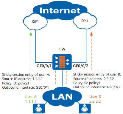
After the sticky session function is enabled and a link is selected for the Internet access traffic of a user, the FW generates a sticky session entry accordingly. If new traffic matches the sticky session entry, the FW will forward the traffic out of the outgoing interface recorded in the sticky session entry. In doing so, the traffic of the same user is always forwarded through the same link.
The source IP address-based sticky session is used as an example for describing the sticky session mechanism. As shown in Figure 5, when the Internet access traffic of user A goes through the first round of intelligent uplink selection, a sticky session entry will be generated, recording the source IP address, matched intelligent route selection policy ID, and outbound interface. When user A initiates connections again, the FW will look up the sticky session entry based on the traffic source IP address and matched intelligent route selection policy ID and forwards the traffic from the outbound interface recorded in the sticky session entry. In this way, the traffic of user A is always forwarded from the same outbound interface.