Understanding Smart DNS
This section describes the overview and implementation of smart DNS.
Overview
An enterprise network has a DNS server. The DNS server has the mappings between the domain name of a Web server and one or multiple public IP addresses. When a user accesses the domain name to connect to the Web server, the packet destination address after resolution is the public IP address of the Web server. The FW then uses the NAT Server function to map the packet destination address to the private address of the Web server. But the IP address after DNS resolution may belong to a different ISP from the user's IP address, causing access delay and inter-ISP settlement. Or multiple users may access the Web server using the same link, causing link congestion.
You can configure the smart DNS function for the FW to intelligently change the resolved address in DNS reply packets, so that each user can have the most appropriate address after resolution, that is, address on the same ISP network as the user. The user initiates access traffic to this address, so that the user traffic is directly forwarded to a specific web server dedicated for the ISP network where the user resides. This ensures the shortest web access delay and best service experience.
Based on the scenario where one or multiple web servers are deployed on the intranet, smart DNS can be divided into the following modes:
- When only one web server is deployed on an enterprise network, that is the mapping between the domain name of the Web server and one IP address of this deployed web server is configured on the DNS server, configure single-server smart DNS.
- When multiple web servers are deployed on an enterprise network, that is the mapping between the domain name of the Web server and multiple IP addresses of deployed web servers are configured on the DNS server, configure multi-server smart DNS.
Smart DNS must work with the NAT server function and sticky load balancing.
- The NAT server function is configured to map the destination address of an access packet from the public address to the private address of the web server.
- After sticky load balancing is configured and DNS response packets are forwarded, the device uses the inbound interface as the outbound interface for response packets instead of searching for the outbound interface based on the routing table. This prevents slow access speed or service interruption caused by inconsistent forward and return paths.

If the Web server address is a public IP address, you do not need to configure NAT Server.
Single-server Smart DNS
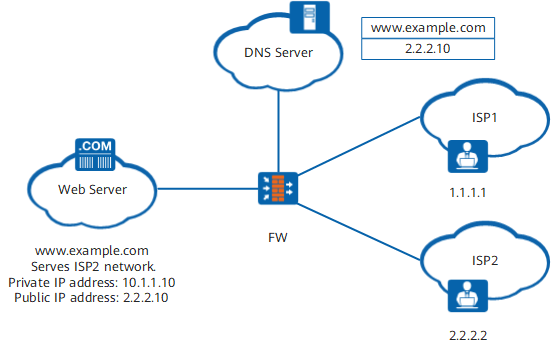
As shown in Figure 1, the enterprise or data center is connected to multiple ISP networks through several links. The private address of the web server is 10.1.1.10, and the public address of the web server is 2.2.2.10. The intranet DNS server has only mappings between the domain names (such as www.example.com) and public addresses (such as 2.2.2.10) of web servers.
When users on ISP2 access a web server on the intranet through domain name www.example.com, the domain name is mapped to IP address 2.2.2.10. The FWthen uses the NAT server function to translate the destination address of packets from 2.2.2.10 to the private address (10.1.1.10) of the NAT server.
When smart DNS is not configured and a user from another ISP network (such as ISP1 users) accesses the Web service provided by the enterprise through domain name www.example.com, the address that the DNS server provides after domain name resolution is 2.2.2.10, which resides on a different ISP network as the user's IP address (the ISP1 user address is 1.1.1.1). Therefore, the traffic of ISP1 user needs to make a detour on ISP2 network to reach the Web server, which increases the service access delay and inter-ISP settlement. Besides, all traffic from external users to the Web server is forwarded over ISP2 network. This may cause network congestion on the link from the FW to ISP2 network, but other links (such as ISP1 link) are idle.
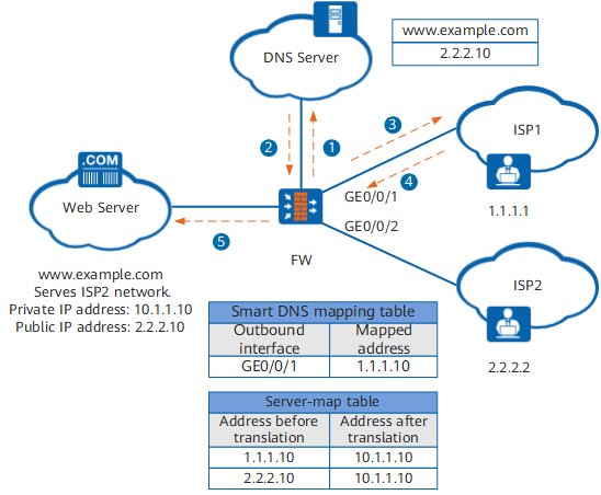
To resolve the preceding problem, you can configure ISP egress-based smart DNS for ISP1 users, so that the FW can map the resolved address to an address on ISP1 network (such as 1.1.1.10 obtained from ISP1 network). In this way, ISP1 users can access the web server directly from ISP1 network without taking a detour on ISP2 network.
- The ISP1 user sends a DNS request to access the web server through domain name www.example.com.
- The DNS server returns resolved IP address 2.2.2.10.
- According to the smart DNS mapping table, the FW changes the IP address in the DNS reply packet to 1.1.1.10 that belongs to the same ISP network as the ISP1 user. Outbound interface GigabitEthernet 0/0/1 in the mapping table is mapped to address 1.1.1.10.
- The ISP1 user initiates a packet destined to 1.1.1.10 for access. The packet reaches the FW through ISP1 network.
- With the NAT server function, the FW translates the destination address (1.1.1.10) of the packet into the private address (10.1.1.10) of the web server.
As for users on ISP2 network, the FW retains the address returned by the DNS server unchanged, namely, 2.2.2.10. With the NAT server function, the FW translates the destination address (2.2.2.10) of the packet into the private address (10.1.1.10) of the web server. Then ISP2 users can access the web server through ISP2 network. In this way, idle ISP1 links or congested ISP2 links no longer exist, and the user access speed and user experience are increased.
- The ISP1 user sends a DNS request to access the web server through domain name www.example.com.
- The DNS server returns resolved IP address 2.2.2.10.
- According to the smart DNS mapping table, the FW changes the IP address in the DNS reply packet to 1.1.1.9 or 1.1.1.10 in round robin mode. Outbound interface GigabitEthernet 0/0/1 in the mapping table is mapped to 1.1.1.9 and 1.1.1.10.
- The ISP1 user initiates a packet destined to 1.1.1.9 or 1.1.1.10 for access. The packet reaches the FW.
- With the NAT server function, the FW translates the destination address (1.1.1.9 or 1.1.1.10) of the packet into the private address (10.1.1.10) of the web server.

Multi-server Smart DNS
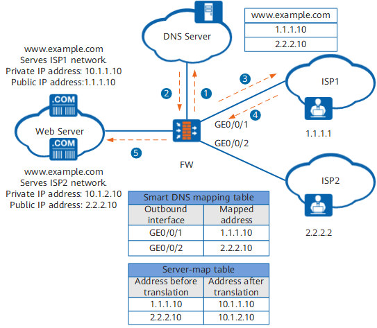
As shown in Figure 4, a large enterprise or data center provides the Web service (such as website access) for external users and usually provides multiple Web server addresses (1.1.1.10 and 2.2.2.10) for users on different ISP networks to access. The DNS server of the enterprise or data center has the mapping between multiple Web service domain names and multiple server addresses.
If smart DNS is not configured and a user of one ISP (such as ISP1) enters a domain name to access the Web service (such as www.example.com), the user initiates a DNS request to the DNS server on the intranet. The DNS server resolves the domain name and returns multiple server addresses (1.1.1.10 and 2.2.2.10) to the user. The ISP1 user selects one of them randomly to initiate an access, but the selected server address may belong to the other ISP (the ISP1 user may accidentally select the ISP server address 2.2.2.10). As a result, the ISP1 user needs to make a detour on ISP2 network before reaching the server, which increases the service access delay and inter-ISP settlement.
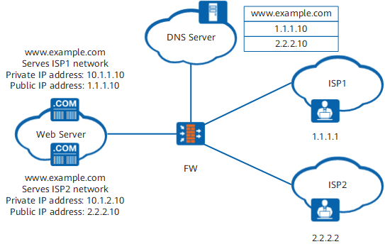
If you configure ISP egress-based smart DNS, the FW will return only one server address to each user, and the server address is on the same ISP network as the user. In this way, the user does not need to make a detour on other ISP networks to access the Web server.
- The ISP1 user sends a DNS request to access the web server through domain name www.example.com.
- The DNS server returns resolved IP addresses 1.1.1.10 and 2.2.2.10.
- According to the smart DNS mapping table, the FW changes the IP address in the DNS reply packet to 1.1.1.10. Outbound interface GigabitEthernet 0/0/1 in the mapping table is mapped to address 1.1.1.10.
- The ISP1 user sends a packet destined for IP address 1.1.1.10 for access. The packet reaches the FW. In this way, ISP1 users can access the web server directly from ISP1 network without taking a detour on ISP2 network, which increases the user access speed and user experience.
- With the NAT server function, the FW translates the destination address (1.1.1.10) of the packet into the private address (10.1.1.10) of the web server.
Similarly, when an ISP2 user accesses the web server through domain name www.example.com, the FW changes the IP address in the DNS reply packet to 2.2.2.10 according to the smart DNS mapping table. The ISP2 initiates a packet destined to IP address 2.2.2.10 for access. With the NAT server function, the FW translates the destination IP address (2.2.2.10) of the packet into the private address (10.1.2.10) of the web server.
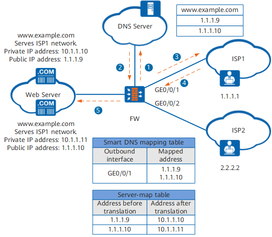
- The ISP1 user sends a DNS request to access the web server through domain name www.example.com.
- The DNS server returns resolved IP addresses 1.1.1.9 and 1.1.1.10.
- According to the smart DNS mapping table, the FW changes the IP address in the DNS reply packet to 1.1.1.9 or 1.1.1.10 in round robin mode. Outbound interface GigabitEthernet 0/0/1 in the mapping table is mapped to 1.1.1.9 and 1.1.1.10.
- The ISP1 user initiates a packet destined to 1.1.1.9 or 1.1.1.10 for access. The packet reaches the FW.
- With the NAT server function, the FW translates the destination address (1.1.1.9 or 1.1.1.10) of the packet into the private address (10.1.1.10 or 10.1.1.11) of the web server.