CLI: Example for Configuring IPSec Intelligent Link Selection (Link Switchover Based on the Route Status)
As the gateway of a branch, the FW uses the IPSec intelligent link selection function for dynamic IPSec tunnel switchover.
Networking Requirements
As shown in Figure 1, the headquarters and branch connect to the Internet through FW_A and FW_B, respectively. FW_A connects to the Internet through one link, and FW_B connects to the Internet through two links and has OSPF running at its egress.
Requirements are as follows:
- An IPSec tunnel is established between FW_A and FW_B for the communication between the headquarters and branch.
- FW_B first uses Link 1 to establish an IPSec tunnel to the headquarters. When Link 1 is faulty, the route from FW_B to FW_A through Link 1 disappears. FW_B automatically switches the IPSec tunnel to Link 2 based on the route change.
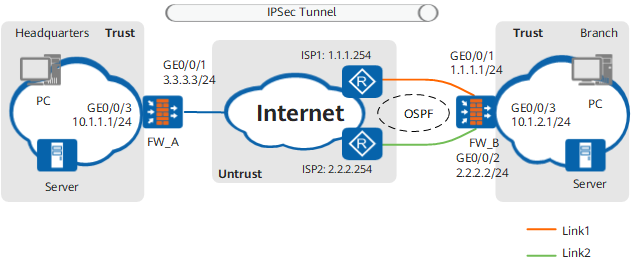
Data Planning
Item |
FW_A |
FW_B |
|
|---|---|---|---|
WAN interface |
Interface number: GigabitEthernet 0/0/1 IP address: 3.3.3.3/24 Security zone: Untrust |
|
|
LAN interface |
Interface number: GigabitEthernet 0/0/3 IP address: 10.1.1.1/24 Security zone: Trust |
Interface number: GigabitEthernet 0/0/3 IP address: 10.1.2.1/24 Security zone: Trust |
|
IPSec policy type |
Template mode |
IKE mode + IPSec intelligent link selection |
|
IPSec proposal |
Encapsulation mode |
Tunnel mode |
Tunnel mode |
Security protocol |
ESP |
ESP |
|
ESP authentication algorithm |
SHA2-256 |
SHA2-256 |
|
ESP encryption algorithm |
AES-256 |
AES-256 |
|
IKE proposal |
Authentication method |
Pre-shared key |
Pre-shared key |
Authentication algorithm |
SHA2-256 |
SHA2-256 |
|
Encryption algorithm |
aes-128 |
aes-128 |
|
IKE peer |
Negotiation mode |
Main mode |
Main mode |
Pre-shared key |
Admin@123 |
Admin@123 |
|
Identity type |
IP address |
IP address |
|
Peer IP address |
Unspecified |
3.3.3.3 |
|
Version |
V1 |
V1 |
|
Procedure
- Configure FW_B (branch).
- Configure security policies to allow specific subnets
to communicate.
# Configure security policies between the Trust zone and the Untrust zone. Ensure that packets can pass through FW_B before encapsulation and after decapsulation.
[FW_B] security-policy
[FW_B-policy-security] rule name 1
[FW_B-policy-security-rule-1] source-zone trust
[FW_B-policy-security-rule-1] destination-zone untrust
[FW_B-policy-security-rule-1] source-address 10.1.2.0 24
[FW_B-policy-security-rule-1] destination-address 10.1.1.0 24
[FW_B-policy-security-rule-1] action permit
[FW_B-policy-security-rule-1] quit
[FW_B-policy-security] rule name 2
[FW_B-policy-security-rule-2] source-zone untrust
[FW_B-policy-security-rule-2] destination-zone trust
[FW_B-policy-security-rule-2] source-address 10.1.1.0 24
[FW_B-policy-security-rule-2] destination-address 10.1.2.0 24
[FW_B-policy-security-rule-2] action permit
[FW_B-policy-security-rule-2] quit
# Configure security policies between the Local zone and the Untrust zone. Ensure that IKE negotiation packets can normally pass through FW_B.

The local-untrust interzone policy controls whether IKE negotiation packets can pass through the FW. This policy can use the source and destination addresses, protocol, or port as the matching condition. In this example, the source and destination addresses are used as the matching condition. To use the protocol or port as the matching condition, you need to enable ESP and port 500 for UDP (port 4500 also in NAT traversal scenarios).
[FW_B-policy-security] rule name 3
[FW_B-policy-security-rule-3] source-zone local
[FW_B-policy-security-rule-3] destination-zone untrust
[FW_B-policy-security-rule-3] source-address 1.1.1.1 32
[FW_B-policy-security-rule-3] source-address 2.2.2.2 32
[FW_B-policy-security-rule-3] destination-address 3.3.3.3 32
[FW_B-policy-security-rule-3] action permit
[FW_B-policy-security-rule-3] quit
[FW_B-policy-security] rule name 4
[FW_B-policy-security-rule-4] source-zone untrust
[FW_B-policy-security-rule-4] destination-zone local
[FW_B-policy-security-rule-4] source-address 3.3.3.3 32
[FW_B-policy-security-rule-4] destination-address 1.1.1.1 32
[FW_B-policy-security-rule-4] destination-address 2.2.2.2 32
[FW_B-policy-security-rule-4] action permit
[FW_B-policy-security-rule-4] quit
- Configure IPSec.
# Configure an ACL to define the data flow to be protected.
[FW_B] acl 3000
[FW_B-acl-adv-3000] rule permit ip source 10.1.2.0 0.0.0.255 destination 10.1.1.0 0.0.0.255
[FW_B-acl-adv-3000] quit
# Configure an IPSec proposal named tran1.
[FW_B] ipsec proposal tran1
[FW_B-ipsec-proposal-tran1] encapsulation-mode tunnel
[FW_B-ipsec-proposal-tran1] transform esp
[FW_B-ipsec-proposal-tran1] esp authentication-algorithm sha2-256
[FW_B-ipsec-proposal-tran1] esp encryption-algorithm aes-256
[FW_B-ipsec-proposal-tran1] quit
# Configure an IKE proposal numbered 10.
[FW_B] ike proposal 10
[FW_B-ike-proposal-10] authentication-method pre-share
[FW_B-ike-proposal-10] authentication-algorithm sha2-256
[FW_B-ike-proposal-10] encryption-algorithm aes-128
[FW_B-ike-proposal-10] quit
# Configure IKE peers.
[FW_B] ike peer a1
[FW_B-ike-peer-a1] ike-proposal 10
[FW_B-ike-peer-a1] remote-address 3.3.3.3
[FW_B-ike-peer-a1] pre-shared-key Admin@123
[FW_B-ike-peer-a1] undo version 2
[FW_B-ike-peer-a1] quit
# Create an IPSec policy group named map1.
[FW_B] ipsec policy map1 10 isakmp
[FW_B-ipsec-policy-isakmp-map1-10] security acl 3000
[FW_B-ipsec-policy-isakmp-map1-10] proposal tran1
[FW_B-ipsec-policy-isakmp-map1-10] ike-peer a1
[FW_B-ipsec-policy-isakmp-map1-10] smart-link profile pro1   //Reference the IPSec intelligent uplink selection profile.
[FW_B-ipsec-policy-isakmp-map1-10] route inject dynamic
[FW_B-ipsec-policy-isakmp-map1-10] quit
You do not need to manually apply the IPSec policy that references an IPSec intelligent link selection profile to the interface. After the IPSec link is selected, the FW will automatically apply the IPSec policy that references the IPSec intelligent link selection profile to the local interface specified for the link.
- Configure security policies to allow specific subnets
to communicate.
- Configure OSPF for the Internet router.
For details, see the configuration manual for the corresponding router. You must ensure that FW_B and FW_A are reachable to each other over the Internet by configuring the intermediate router.
- Configure FW_A (headquarters).
- Configure security policies to allow specific subnets
to communicate.
# Configure security policies between the Trust zone and the Untrust zone. Ensure that packets can pass through FW_A before encapsulation and after decapsulation.
[FW_A] security-policy
[FW_A-policy-security] rule name 1
[FW_A-policy-security-rule-1] source-zone trust
[FW_A-policy-security-rule-1] destination-zone untrust
[FW_A-policy-security-rule-1] source-address 10.1.1.0 24
[FW_A-policy-security-rule-1] destination-address 10.1.2.0 24
[FW_A-policy-security-rule-1] action permit
[FW_A-policy-security-rule-1] quit
[FW_A-policy-security] rule name 2
[FW_A-policy-security-rule-2] source-zone untrust
[FW_A-policy-security-rule-2] destination-zone trust
[FW_A-policy-security-rule-2] source-address 10.1.2.0 24
[FW_A-policy-security-rule-2] destination-address 10.1.1.0 24
[FW_A-policy-security-rule-2] action permit
[FW_A-policy-security-rule-2] quit
# Configure security policies between the Local zone and the Untrust zone. Ensure that IKE negotiation packets can normally pass through FW_A.
The local-untrust interzone policy controls whether IKE negotiation packets can pass through the FW. This policy can use the source and destination addresses, protocol, or port as the matching condition. In this example, the source and destination addresses are used as the matching condition. To use the protocol or port as the matching condition, you need to enable ESP and port 500 for UDP (port 4500 also in NAT traversal scenarios).
[FW_A-policy-security] rule name 3
[FW_A-policy-security-rule-3] source-zone local
[FW_A-policy-security-rule-3] destination-zone untrust
[FW_A-policy-security-rule-3] source-address 3.3.3.3 32
[FW_A-policy-security-rule-3] destination-address 1.1.1.1 32
[FW_A-policy-security-rule-3] destination-address 2.2.2.2 32
[FW_A-policy-security-rule-3] action permit
[FW_A-policy-security-rule-3] quit
[FW_A-policy-security] rule name 4
[FW_A-policy-security-rule-4] source-zone untrust
[FW_A-policy-security-rule-4] destination-zone local
[FW_A-policy-security-rule-4] source-address 1.1.1.1 32
[FW_A-policy-security-rule-4] source-address 2.2.2.2 32
[FW_A-policy-security-rule-4] destination-address 3.3.3.3 32
[FW_A-policy-security-rule-4] action permit
[FW_A-policy-security-rule-4] quit
[FW_A-policy-security] quit
- Configure security policies to allow specific subnets
to communicate.
Verification
After the configuration is complete, run the display ipsec smart-link profile command on FW_B. The command output shows that FW_B at the branch first uses Link 1 (1.1.1.1 -> 3.3.3.3) to establish an IPSec tunnel.
<FW_B> display ipsec smart-link profile name pro1
===========================================
 Name                      :pro1
 Switch mode               :route-based
 State                     :enable
 IPSec policy alias        :map1-10
 link list:
 ID local-address   remote-address  loss(%) delay(ms)  state
 1  1.1.1.1         3.3.3.3         --        --       active
 2  2.2.2.2         3.3.3.3         --        --       inactive
===========================================
Run the display ike sa and display ipsec sa commands on FW_A and FW_B to display the established IKE and IPSec SAs. Take FW_B as an example. If the following information is displayed, the IKE and IPSec SAs are successfully established.
<FW_B> display ike sa IKE SA information : Conn-ID Peer VPN Flag(s) Phase RemoteType RemoteID ------------------------------------------------------------------------------------------------------------------------------------ 66 3.3.3.3:500 RD|ST|A v1:2 IP 3.3.3.3 65 3.3.3.3:500 RD|ST|A v1:1 IP 3.3.3.3 Number of IKE SA : 2 ------------------------------------------------------------------------------------------------------------------------------------ Flag Description: RD--READY ST--STAYALIVE RL--REPLACED FD--FADING TO--TIMEOUT HRT--HEARTBEAT LKG--LAST KNOWN GOOD SEQ NO. BCK--BACKED UP M--ACTIVE S--STANDBY A--ALONE NEG--NEGOTIATING<FW_B> display ipsec sa ipsec sa information: =============================== Interface: GigabitEthernet0/0/1 =============================== ----------------------------- IPSec policy name: "map1" Sequence number : 10 Acl group : 3000 Acl rule : 5 Mode : ISAKMP ----------------------------- Connection ID : 66 Encapsulation mode: Tunnel Holding time : 0d 0h 8m 52s Tunnel local : 1.1.1.1:500 Tunnel remote : 3.3.3.3:500 Flow source : 10.1.2.0/255.255.255.0 0/0 Flow destination : 10.1.1.0/255.255.255.0 0/0 [Outbound ESP SAs] SPI: 194713812 (0xb9b18d4) Proposal: ESP-ENCRYPT-AES-256 ESP-AUTH-SHA2-256-128 SA remaining key duration (kilobytes/sec): 5242880/3068 Max sent sequence-number: 11 UDP encapsulation used for NAT traversal: N SA encrypted packets (number/bytes): 10/840 [Inbound ESP SAs] SPI: 190232433 (0xb56b771) Proposal: ESP-ENCRYPT-AES-256 ESP-AUTH-SHA2-256-128 SA remaining key duration (kilobytes/sec): 5242880/3068 Max received sequence-number: 1 UDP encapsulation used for NAT traversal: N SA decrypted packets (number/bytes): 5/420 Anti-replay : Enable Anti-replay window size: 1024
Shut down GE0/0/1 on FW_B and then run the display ipsec smart-link profile command on FW_B. The command output shows that FW_B automatically uses Link 2 (2.2.2.2 -> 3.3.3.3) to establish an IPSec tunnel.
<FW_B> display ipsec smart-link profile name pro1
===========================================
 Name                      :pro1
 Switch mode               :route-based
 State                     :enable
 IPSec policy alias        :map1-10
 link list:
 ID local-address   remote-address  loss(%) delay(ms)  state
 1  1.1.1.1         3.3.3.3         --        --       inactive
 2  2.2.2.2         3.3.3.3         --        --       active
===========================================
Configuration Scripts
Configuration script of FW_A:
#
acl number 3000
 rule 5 permit ip source 10.1.1.0 0.0.0.255 destination 10.1.2.0 0.0.0.255
#
ike proposal 10
 encryption-algorithm aes-128
 dh group14
 authentication-algorithm sha2-256
 authentication-method pre-share
#
ike peer b
 pre-shared-key %$%$921NG0I(@0aT8y@GhOS97G>5%$%$
 ike-proposal 10
 undo version 2
#
ipsec proposal tran1
 esp authentication-algorithm sha2-256
 esp encryption-algorithm aes-256
#
ipsec policy-template map_temp 1
 security acl 3000
 ike-peer b
 proposal tran1
 route inject dynamic
#
ipsec policy map1 10 isakmp template map_temp
#
interface GigabitEthernet0/0/1
 ip address 3.3.3.3 255.255.255.0
 ipsec policy map1
#
interface GigabitEthernet0/0/3
 ip address 10.1.1.1 255.255.255.0
#
firewall zone trust
 set priority 85
 add interface GigabitEthernet0/0/3
#
firewall zone untrust
 set priority 5
 add interface GigabitEthernet0/0/1
#
security-policy
 rule name 1
  source-zone trust
  destination-zone untrust
  source-address 10.1.1.0 mask 255.255.255.0
  destination-address 10.1.2.0 mask 255.255.255.0
  action permit
 rule name 2
  source-zone untrust
  destination-zone trust
  source-address 10.1.2.0 mask 255.255.255.0
  destination-address 10.1.1.0 mask 255.255.255.0
  action permit
 rule name 3
  source-zone local
  destination-zone untrust
  source-address 3.3.3.3 mask 255.255.255.255
  destination-address 1.1.1.1 mask 255.255.255.255
  destination-address 2.2.2.2 mask 255.255.255.255
  action permit
 rule name 4
  source-zone untrust
  destination-zone local
  source-address 1.1.1.1 mask 255.255.255.255
  source-address 2.2.2.2 mask 255.255.255.255
  destination-address 3.3.3.3 mask 255.255.255.255
  action permit
Configuration script of FW_B:
#
acl number 3000
 rule 5 permit ip source 10.1.2.0 0.0.0.255 destination 10.1.1.0 0.0.0.255
#
ike proposal 10
 encryption-algorithm aes-128
 dh group14
 authentication-algorithm sha2-256
 authentication-method pre-share
#
ike peer a1
 undo version 2
 pre-shared-key %^%#t)H+5Zh1U%O5M~G{~Vg4o^T)7FEJUS{zD[Q@\(&3%^%#
 ike-proposal 10
 remote-address 3.3.3.3
#
ipsec proposal tran1
 esp authentication-algorithm sha2-256
 esp encryption-algorithm aes-256
#
ipsec smart-link profile pro1
 link-switch-mode route-based
 link 1 interface GigabitEthernet0/0/1 local 1.1.1.1 remote 3.3.3.3
 link 2 interface GigabitEthernet0/0/2 local 2.2.2.2 remote 3.3.3.3
#
ipsec policy map1 10 isakmp
 security acl 3000
 ike-peer a1
 proposal tran1
 smart-link profile pro1
 route inject dynamic
#
interface GigabitEthernet0/0/1
 ip address 1.1.1.1 255.255.255.0
#
interface GigabitEthernet0/0/2
 ip address 2.2.2.2 255.255.255.0
#
interface GigabitEthernet0/0/3
 ip address 10.1.2.1 255.255.255.0
#
firewall zone trust
 set priority 85
 add interface GigabitEthernet0/0/3
#
firewall zone untrust
 set priority 5
 add interface GigabitEthernet0/0/1
 add interface GigabitEthernet0/0/2
#
security-policy
 rule name 1
  source-zone trust
  destination-zone untrust
  source-address 10.1.2.0 mask 255.255.255.0
  destination-address 10.1.1.0 mask 255.255.255.0
  action permit
 rule name 2
  source-zone untrust
  destination-zone trust
  source-address 10.1.1.0 mask 255.255.255.0
  destination-address 10.1.2.0 mask 255.255.255.0
  action permit
 rule name 3
  source-zone local
  destination-zone untrust
  source-address 1.1.1.1 mask 255.255.255.255
  source-address 2.2.2.2 mask 255.255.255.255
  destination-address 3.3.3.3 mask 255.255.255.255
  action permit
 rule name 4
  source-zone untrust
  destination-zone local
  source-address 3.3.3.3 mask 255.255.255.255
  destination-address 1.1.1.1 mask 255.255.255.255
  destination-address 2.2.2.2 mask 255.255.255.255
  action permit
#
ospf 1 router-id 1.1.1.1
 area 0.0.0.0
  network 1.1.1.0 0.0.0.255
  network 2.2.2.0 0.0.0.255