Configuring IPSec Intelligent Link Selection
When the FW serves as a gateway in a branch office, it can implement dynamic switchovers among multiple IPSec tunnels using IPSec intelligent link selection. This section describes how to configure IPSec intelligent link selection on the web UI.
Procedure
- Choose .
- Click Add to add an IPSec policy.
- Select Site-to-site in Scenario.
- Select IPSec smart-link.
- In Policy Name, configure the IPSec policy name.
- Configure links for IPSec intelligent link selection.
Parameter
Description
Local Interface
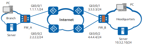
Select a public interface from the drop-down list for the local end, such as GE0/0/1 and GE0/0/2 of FW_A in Figure 1.
Local Interface IP
Select a local IP address from the drop-down list to establish a tunnel with the peer device. If multiple IP addresses are configured for Local Interface, you can select any of the IP addresses as long as it is accessible to the peer device.
Peer IP Address
Specify the public interface address of the peer, such as 3.3.3.3 and 4.4.4.4 on FW_B in Figure 1.
NOTE:A maximum of 10 peer IP addresses can be specified.
Adjust link priorities
The FW groups together the local and peer interface IP addresses to provide multiple links for IPSec intelligent link selection. For example, as shown in Figure 1, four links are available for IPSec intelligent link selection based on the permutation and combination of the local and peer interface IP addresses, namely, 1.1.1.1->3.3.3.3, 1.1.1.1->4.4.4.4, 2.2.2.2->3.3.3.3, and 2.2.2.2->4.4.4.4.
The FW determines the priorities of the links based on the regions and operators to which the local and peer interface IP addresses belong. The priorities of the links are as follows: link with the local and peer interface IP addresses of the same region and operator > link with the local and peer interface IP addresses of the same region but different operators > link with the local and peer interface IP addresses of the same operator but different regions > link with the local and peer interface IP addresses of different regions and operators.
You can click Adjust link priorities to view links available for IPSec intelligent link selection and click
 and
and  to adjust the link sequence.NOTE:
If an IP address is available in China, the FW can identify the city by default; otherwise, the FW can identify the country only. If the region of an IP address identified by the FW is not correct or specific, adjust them. For details, see Configuring Regions and Region Groups Using the Web UI.
By default, the FW can identify the IP addresses of China Mobile, China Unicom, China Telecom, and China Education and Research Network (CERNET). If the operator of an IP address identified by the FW is incorrect, change it using Address Library File. For details, see Configuring ISP Link Selection.
Automatic link switchback
The automatic link switchback switch can be used to enable automatic switchback to a high-priority link. This function is disabled by default.
After automatic switchback to a high-priority link in IPSec intelligent link selection is enabled, the FW continuously detects the quality of the high-priority link after the IPSec tunnel is switched to the backup link. If the quality of the high-priority link continuously meets the requirements within the configured switchback delay, the FW automatically switches the IPSec tunnel back to the high-priority link.
NOTE:After automatic switchback to a high-priority link is enabled, the tunnel detection parameters in the IPSec intelligent link selection rule on the local device and the data flows to be encrypted in the IPSec policy on the peer device are different in the following configurations compared with those before the automatic switchback function is enabled:
- The link detection addresses must be configured in the IPSec intelligent link selection rule on the local device. The source and destination IP addresses of the detection packets can not be the IP addresses of the interfaces at the two ends of the IPSec tunnel, they can be IP addresses contained in the data flows to be encrypted.
- The IPSec policy of the peer device must be configured with to-be-encrypted data flows whose source IP address is the destination IP address of the destination packets, destination IP address is the source IP address of the detection packets, and protocol type is ICMP. (For example, if the source IP address of the detection packets on the local device is 1.1.1.1 and the destination IP address is 2.2.2.2, then the source IP address of the data flows to be encrypted is 2.2.2.2, the destination IP address is 1.1.1.1, the protocol type is ICMP, and the action is Encrypt.) In addition, the link detection addresses are configured on the local device and the FW does not use the IP addresses of the interfaces at the two ends of the link as the source address and destination address of the detection packets. Therefore, you do not need to configure to-be-encrypted data flows that use the IP addresses of the interfaces at the two ends of the IPSec tunnel as the source and destination IP addresses on the peer device.
Switchback delay
Set the delay of automatic switchback to a high-priority link. The link can be automatically switched back only when the quality (packet loss rate and delay) of the high-priority link continuously meets the requirements within the configured switchback delay.
By default, the switchback delay is 180 seconds.

The link to [Add Security Policy] is provided on the web UI. You can click the link to access the Add Security Policy page and rapidly create a security policy based on the configured IPSec policy to permit tunnel negotiation packets. In addition, the Add Security Policy page support Switch Source and Destination and OK and Copy for configuring security policies for forward and return traffic.
- Configure the data flows to be encrypted through the IPSec tunnel.
In common cases, only a bunch of data flows need to be encrypted before they are sent to the peer, and the rests are sent directly through the Internet. To avoid those data flows to be transmitted directly through the Internet entering the tunnel, you need to configure certain rules to restrict the them.
You can configure multiple rules in a list. Data flows match the rules from top to bottom. If a match is found, data flows are processed according to the specified action, and the matching process ends.
Parameter
Description
Source Address/Address-set
Specify the source address from which the data flows to be encrypted through the tunnel are originated. In common practices, the source address is usually the address of the intranet subnet to be protected.
You can enter an IP address (such as 192.168.1.1), network segment (such as 192.168.1.0/24 or 192.168.1.0/255.255.255.0), or address group.
Address groups are usually used when an intranet has multiple network segments, so as to reduce encrypted data flow configuration and increase configuration efficiency.
Members cannot be address groups with consecutive IP address segments.
Destination Address/Address-set
Specify the destination address for which the data flows to be encrypted through the tunnel are destined. In common practices, the destination address is usually the address of the requested subnet on the peer intranet.
You can enter an IP address (such as 10.1.1.1), network segment (such as 10.1.1.0/24 or 10.1.1.0/255.255.255.0), or address group.
Address groups are usually used when an intranet has multiple network segments, so as to reduce encrypted data flow configuration and increase configuration efficiency.
Members cannot be address groups with consecutive IP address segments.
Protocol
Specify the protocol through which the data flows are transmitted, and then the TCP or UDP port for encrypting traffic of specific service.
For example, you can specify TCP port 80 to encrypt HTTP traffic, or UDP port 69 to encrypt TFTP traffic.
If you do not know the protocol and port or there is no need to perform protocol-based restriction, leave this parameter unspecified or set it to any.
Source Port
This parameter is available if you select TCP, SCTP or UDP in Protocol.
Specify the source port number from which the data flows to be encrypted through the tunnel are originated.
Destination Port
This parameter is available if you select TCP, SCTP or UDP in Protocol.
Specify the destination port number for which the data flows to be encrypted through the tunnel are destined.
Action
Specify the action for data flows that match the preceding conditions.
Encrypt indicates that the data flows are allowed to be encrypted through the tunnel.
Not Encrypt indicates that the data flows are not allowed to be encrypted through the tunnel.
The Not Encrypt action is used to exempt traffic of some clients from encryption. For example, to encrypt the traffic from all hosts on subnet 192.168.1.0/24 except a host at 192.168.1.2, configure a rule for exempting traffic of the host at 192.168.1.2 from encryption and a rule for encrypting traffic of hosts on subnet 192.168.1.0/24.
The link to [Add Security Policy] is provided on the web UI. You can click the link to access the Add Security Policy page and rapidly create a security policy based on the configured data flows to be encrypted to permit encrypted traffic. In addition, the Add Security Policy page support Switch Source and Destination and OK and Copy for configuring security policies for forward and return traffic.
You can select Reverse Route Injection if necessary. If Reverse Route Injection is selected, the device automatically installs the routes pointed to the peer network. This function is usually configured on the HQ gateway connected to multiple branches.
You can set the Priority if necessary. For example, if other routes to the same destination exist on the device, you can specify the same priority for them to implement load balancing, or different priorities to implement route backup.
- Configure tunnel detection parameters.
The FW prefers the link with the highest priority to establish an IPSec tunnel. After establishing the IPSec tunnel, the FW sends ICMP packets to detect the delay and packet loss rate on the IPSec tunnel. If the delay or packet loss rate is greater than Link quality indicator of the tunnel, the FW uses the link with the second highest priority to establish a new IPSec tunnel. Then FW continues to detect the delay and packet loss rate on the new tunnel. If the delay or packet loss rate is still greater than Link quality indicator, FW continues to switch to another link until the delay or packet loss rate is within the normal range or the number of switchover cycles reaches the upper threshold.
Parameter
Description
Tunnel detection
After you select it, the link quality detection function is enabled, and links can be switched on the basis of link quality.
After you deselect it, link quality detection and link switchover stop. The established IPSec tunnel continues to take effect.
Switching times
Indicates the upper threshold of link switchover cycles.
If links 1 through 4 exist, 1->2->3->4 is a complete link switchover cycle. If the number of cyclic link switchovers reaches the upper threshold and the loop switching duration from the highest priority link to the lowest priority link is within 10 minutes, the FW stops link detection and cyclic switchovers for 10 minutes switches traffic to the link with the lowest packet loss ratio. Then, the FW starts link detection and cyclic link switchovers again.
NOTE:- If the packet loss ratio is 100% for all links, the link switchover stops at the last link.
- If the Switching times is set to 0, the FW will never stop the link detection and cyclic link switchovers.
Detection packets
Indicates the number of link quality detection packets sent within an detection cycle.
If Detection packets is 20, the FW will calculate the delay and packet loss rate after sending 20 link quality detection packets and compare them with those specified in Link quality indicator. If the delay or packet loss rate exceeds the upper threshold in Link quality indicator, a link switchover is triggered.
Sending interval
Indicates the interval for sending link quality detection packets.
Link Detection Packet
You can select this item to define source and destination IP addresses for link quality detection packets.
If you do not select this item, the FW uses the local and peer IPSec tunnel interface IP addresses as the source and destination IP addresses of link quality detection packets respectively by default.
Detection Source IP
You can configure this parameter only after setting Link Detection Packet.
The source IP address of a detection packet can be any one as long as the address and peer address are reachable to each other.
Detection Destination IP
You can configure this parameter only after setting Link Detection Packet.
The destination IP address of a detection packet can be either the address of a device on the remote intranet or an interface IP address of the remote gateway.
Link quality indicator
This parameter includes Packet loss ratio and Delay.
The packet loss rate is calculated based on this formula: Packet loss rate = Number of discarded packets within a link quality detection cycle/Total number of link quality detection packets within a link quality detection cycle.
The delay is calculated based on the formula: Delay = Time when a response packet is received - Time when a detection packet is sent. The FW calculates the delay of each detection packet within a detection cycle and takes an average.
- Click Apply. The newly configured IPSec policy is displayed in the policy list.