Example for Configuring the 6RD Tunnel (6RD Domain-6RD Domain)
This section provides an example for configuring a 6RD tunnel by manually setting the source IPv4 address of the tunnel on the 6RD Customer Edge (CE) device. Then hosts on the IPv6 networks can communicate through the 6RD tunnel.
Networking Requirements
As shown in Figure 1, FW_A and FW_B support the IPv6/IPv4 dual stack and connect to the IPv6 networks and the IPv4 network. FW_A and FW_B are 6RD CE devices, and the connected IPv6 networks are 6RD networks. A 6RD tunnel needs to be established between FW_A and FW_B, so that hosts on the two 6RD domains can communicate.
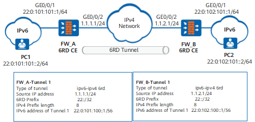
Configuration Roadmap
The configuration roadmap is as follows:
The 6RD CE devices between the IPv6 islands and the IPv4 network support the IPv4/IPv6 dual stack. Therefore, set IPv4 addresses for interfaces on FW_A and FW_B and enable IPv6 packet forwarding.
Set the 6RD tunnel source address and IPv6 address of the tunnel interface on the 6RD CE devices.
FW_A and FW_B are the border devices of the 6RD domains, and the IPv6 address prefixes of interfaces connected to the IPv6 network are assigned by the 6RD delegated prefix. Similarly, the IPv6 address prefixes of PC1 and PC2 are assigned by the 6RD delegated prefix.
Configure routes. (This example uses static routes.)
Procedure
- Configure FW_A.
# Configure an IPv4 address for GE0/0/2.
<FW_A> system-view
[FW_A] interface GigabitEthernet0/0/2
[FW_A-GigabitEthernet0/0/2] ip address 1.1.1.1 24
[FW_A-GigabitEthernet0/0/2] quit
[FW_A] firewall zone untrust
[FW_A-zone-untrust] add interface GigabitEthernet0/0/2
[FW_A-zone-untrust] quit
# Enable the IPv6 packet forwarding function on the 6RD CE.
[FW_A] ipv6# Set an encapsulation type, a source address, a 6RD prefix, and an IPv4 prefix length.
[FW_A] interface tunnel 1
[FW_A-Tunnel1] tunnel-protocol ipv6-ipv4 6rd
[FW_A-Tunnel1] ipv6 enable
[FW_A-Tunnel1] source GigabitEthernet0/0/2
[FW_A-Tunnel1] ipv6-prefix 22::/32
[FW_A-Tunnel1] ipv4-prefix length 8
[FW_A-Tunnel1] quit
[FW_A] firewall zone untrust
[FW_A-zone-untrust] add interface Tunnel1
[FW_A-zone-untrust] quit

After you specify the 6RD prefix and IPv4 prefix length, the 6RD CE automatically calculates the 6RD delegated prefix.
# Display the calculated 6RD delegated prefix.
[FW_A] display interface Tunnel 1
Tunnel1 current state : UP
Line protocol current state : DOWN
Description: Tunnel1 Interface
Route Port,The Maximum Transmit Unit is 1500
Internet protocol processing : disabled
Encapsulation is TUNNEL, loopback not set
Tunnel source 1.1.1.1 (GigabitEthernet0/0/2), destination auto
Tunnel protocol/transport IPv6 over IPv4(6rd)
ipv6 prefix 22::/32
ipv4 prefix length 8
6RD Operational, Delegated Prefix is 22:0:101:100::/56
# Configure an IPv6 address for the tunnel interface based on the 6RD delegated prefix, tunnel source address, and IPv4 prefix length.
[FW_A-Tunnel1] ipv6 address 22:0:101:100::1 56# Configure an IPv6 address for GE0/0/1.
[FW_A] ipv6
[FW_A] interface GigabitEthernet0/0/1
[FW_A-GigabitEthernet0/0/1] ipv6 enable
[FW_A-GigabitEthernet0/0/1] ipv6 address 22:0:101:101::1 64
[FW_A-GigabitEthernet0/0/1] quit
[FW_A] firewall zone trust
[FW_A-zone-trust] add interface GigabitEthernet0/0/1
[FW_A-zone-trust] quit
# Configure a security policy.
[FW_A] security-policy
[FW_A-policy-security] rule name policy1
[FW_A-policy-security-policy1] source-zone trust untrust
[FW_A-policy-security-policy1] destination-zone trust untrust
[FW_A-policy-security-policy1] action permit
[FW_A-policy-security-policy1] quit
[FW_A-policy-security] rule name policy2
[FW_A-policy-security-policy2] source-zone local untrust
[FW_A-policy-security-policy2] destination-zone local untrust
[FW_A-policy-security-policy2] action permit
[FW_A-policy-security-policy2] quit
[FW_A-policy-security] quit
# Configure a route to the 6RD domain connected to FW_B.
[FW_A] ipv6 route-static 22:: 32 Tunnel 1# Configure a static IPv4 route, with the next hop being the gateway address of GigabitEthernet0/0/2 on FW_A (1.1.1.254 in this example).
[FW_A] ip route-static 1.1.2.0 255.255.255.0 1.1.1.254 - Configure an address for of PC1.
# Based on the 6RD delegated prefix, set the address to 22:0:101:101::2 64 for PC1. This address is on the same network segment as that of GE0/0/1. (The method for setting IPv6 addresses is determined by the operating system of PC1.)
- Configure the FW_B.
# Configure an IPv4 address for GE0/0/2.
<FW_B> system-view
[FW_B] interface GigabitEthernet0/0/2
[FW_B-GigabitEthernet0/0/2] ip address 1.1.2.1 24
[FW_B-GigabitEthernet0/0/2] quit
[FW_B] firewall zone untrust
[FW_B-zone-untrust] add interface GigabitEthernet0/0/2
[FW_B-zone-untrust] quit
# Enable the IPv6 packet forwarding function on FW.
[FW_B] ipv6# Set an encapsulation type, a source address, a 6RD prefix, and an IPv4 prefix length.
[FW_B] interface tunnel 1
[FW_B-Tunnel1] tunnel-protocol ipv6-ipv4 6rd
[FW_B-Tunnel1] ipv6 enable
[FW_B-Tunnel1] source GigabitEthernet0/0/2
[FW_B-Tunnel1] ipv6-prefix 22::/32
[FW_B-Tunnel1] ipv4-prefix length 8
[FW_B-Tunnel1] quit
[FW_B] firewall zone untrust
[FW_B-zone-untrust] add interface Tunnel1
[FW_B-zone-untrust] quit
After you specify the 6RD prefix and IPv4 prefix length, the 6RD CE automatically calculates the 6RD delegated prefix.
# Display the calculated 6RD delegated prefix.
[FW_B] display interface Tunnel 1
Tunnel1 current state : UP
Line protocol current state : DOWN
Description:Tunnel1 Interface
Route Port,The Maximum Transmit Unit is 1500
Internet protocol processing : disabled
Encapsulation is TUNNEL, loopback not set
Tunnel source 1.1.2.1(GigabitEthernet0/0/2), destination auto
Tunnel protocol/transport IPV6 over IPv4(6rd)
ipv6 prefix 22::/32
ipv4 prefix length 8
6RD Operational, Delegated Prefix is 22:0:102:100::/56
# Configure an IPv6 address for the tunnel interface based on the 6RD delegated prefix, tunnel source address, and IPv4 prefix length.
[FW_B-Tunnel1] ipv6 address 22:0:102:100::1 56# Configure an IPv6 address for GE0/0/1.
[FW_B] interface GigabitEthernet0/0/1
[FW_B-GigabitEthernet0/0/1] ipv6 enable
[FW_B-GigabitEthernet0/0/1] ipv6 address 22:0:102:101::1 64
[FW_B-GigabitEthernet0/0/1] quit
[FW_B] firewall zone trust
[FW_B-zone-trust] add interface GigabitEthernet0/0/1
[FW_B-zone-trust] quit
# Configure a security policy.
[FW_B] security-policy
[FW_B-policy-security] rule name policy1
[FW_B-policy-security-policy1] source-zone trust untrust
[FW_B-policy-security-policy1] destination-zone trust untrust
[FW_B-policy-security-policy1] action permit
[FW_B-policy-security-policy1] quit
[FW_B-policy-security] rule name policy2
[FW_B-policy-security-policy2] source-zone local untrust
[FW_B-policy-security-policy2] destination-zone local untrust
[FW_B-policy-security-policy2] action permit
[FW_B-policy-security-policy2] quit
[FW_B-policy-security] quit
# Configure a route to the 6RD domain connected to FW_A
[FW_B] ipv6 route-static 22:: 32 Tunnel 1# Configure a static IPv4 route, with the next hop being the gateway address of GigabitEthernet0/0/2 on FW_B (1.1.2.254 in this example).
[FW_B] ip route-static 1.1.1.0 255.255.255.0 1.1.2.254 - Configure an address for PC2.
# Set the address to 22:0:102:101::2 64 for PC2. This address is on the same network segment as that of GE0/0/1. (The method for setting IPv6 addresses is determined by the operating system of PC2.)
Verification
# After you complete the preceding configurations, run the display ipv6 interface tunnel command in any view to check the IPv6 status and configuration of Tunnel1. The command output on the FW is as follows:
[FW_B] display ipv6 interface tunnel 1
Tunnel1 current state : UP
IPv6 protocol current state : UP
IPv6 is enabled, link-local address is FE80::101:101
 Global unicast address(es):
    22:0:102:100::1, subnet is 22:0:102:100::/64
  Joined group address(es):
    FF02::1:FF00:1
    FF02::1:FF01:101
    FF02::2
  MTU is 1500 bytes
  ND reachable time is 30000 milliseconds
  ND retransmit interval is 1000 milliseconds
# Run the ping ipv6 -a 22:0:102:101::1 22:0:101:101::1 command on FW_B to view the tunnel established between FW_A and FW_B and their connectivity.
[FW_B] ping ipv6 -a 22:0:102:101::1 22:0:101:101::1
  PING 22:0:101:101::1 : 56  data bytes, press CTRL_C to break
    Reply from 22:0:101:101::1
    bytes=56 Sequence=1 hop limit=64  time = 1 ms
    Reply from 22:0:101:101::1
    bytes=56 Sequence=2 hop limit=64  time = 1 ms
    Reply from 22:0:101:101::1
    bytes=56 Sequence=3 hop limit=64  time = 1 ms
    Reply from 22:0:101:101::1
    bytes=56 Sequence=4 hop limit=64  time = 1 ms
    Reply from 22:0:101:101::1
    bytes=56 Sequence=5 hop limit=64  time = 1 ms

  --- 22:0:101:101::1 ping statistics ---
    5 packet(s) transmitted
    5 packet(s) received
    0.00% packet loss
    round-trip min/avg/max = 1/1/1 ms
By default, the interface has the access control and management function enabled. Therefore, you need to run the undo service-manage enable command on the FW to disable the access control and management function of the interface so that the FW can be pinged.
Configuration Scripts
Configuration script of FW_A:
#
 sysname FW_A
#
ipv6
#
interface GigabitEthernet0/0/2
 ip address 1.1.1.1 255.255.255.0
#
interface GigabitEthernet0/0/1
 ipv6 enable
 ipv6 address 22:0:101:101::1 64
#
interface Tunnel 1
 tunnel-protocol ipv6-ipv4 6rd
 ipv6 enable
 source GigabitEthernet0/0/2
 ipv6-prefix 22::/32
 ipv4-prefix length 8
 ipv6 address 22:0:101:100::1 56
#
firewall zone trust
 add interface GigabitEthernet0/0/1
#
firewall zone untrust
 add interface GigabitEthernet0/0/2
 add interface tunnel1
#
ip route-static 1.1.2.0 255.255.255.0 1.1.1.254
#
 ipv6 route-static 22:: 32 Tunnel 1
#
security-policy
 rule name policy1
  source-zone trust
  source-zone untrust
  destination-zone trust
  destination-zone untrust
  action permit
 rule name policy2
  source-zone local
  source-zone untrust
  destination-zone local
  destination-zone untrust
  action permit
#
return
Configuration script of FW_B:
#
 sysname FW_B
#
ipv6
#
interface GigabitEthernet0/0/2
 ip address 1.1.2.1 255.255.255.0
#
interface GigabitEthernet0/0/1
 ipv6 enable
 ipv6 address 22:0:102:101::1 64
#
interface Tunnel1
 ipv6 enable
 ipv6 address 22:0:102:100::1 56
 tunnel-protocol ipv6-ipv4 6rd
 source GigabitEthernet0/0/2
 ipv6-prefix 22::/32
 ipv4-prefix length 8
#
firewall zone trust
 add interface GigabitEthernet0/0/1
#
firewall zone untrust
 add interface GigabitEthernet0/0/2
 add interface tunnel1
#
ip route-static 1.1.1.0 255.255.255.0 1.1.2.254
#
ipv6 route-static 22:: 32 Tunnel 1
#
security-policy
 rule name policy1
  source-zone trust
  source-zone untrust
  destination-zone trust
  destination-zone untrust
  action permit
 rule name policy2
  source-zone local
  source-zone untrust
  destination-zone local
  destination-zone untrust
  action permit
#
return