CLI: Example for Sending IPv4 Session Logs to the eLog in Hot Standby Deployment of Mirroring Mode
This section describes how to configure hot standby when service interfaces on two firewalls work at Layer 3 in mirroring mode.
Networking Requirements
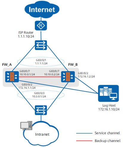
On the network shown in Figure 1, the service interfaces of two FWs work at Layer 3 and are directly connected to switches in both upstream and downstream directions. The FWs are connected to log hosts respectively.
The upstream switch is connected to the carrier network, and the IP address that the carrier assigns to the enterprise is 1.1.1.1 to 1.1.1.5.
It is required that the two FWs form hot standby networking in mirroring mode and intranet users can access the Internet.
In the mirroring mode, the two FWs have the same service interface address and route configuration. Therefore, the two FWs can be considered as one device.
The administrator wants to check PAT-mode IPv4 session logs on the eLog to understand the creation of sessions by packets in a timely manner and, when necessary, perform NAT source tracing.
Configuration Roadmap
Before configuring the mirroring mode, you need to compete network connections and basic configurations of hot standby, but not service interface and interface configurations. The configuration roadmap is described as follows:
- Complete basic hot standby configurations on the two FW, including configuring VGMP groups to monitor service interfaces (hrp track interface), configuring the heartbeat interfaces, and enabling hot standby.
- Enable the mirroring mode on the FWs and complete manual batch backup.
Complete network configurations on one of the FWs to ensure that intranet users can access the Internet.
After the mirroring mode is formed, all configurations (including interface and route configurations) need to be performed on only one FW. These configurations will be automatically backed up to the other FW.
- Configure log hosts and enable log recording on the two FWs.
Procedure
- Configure heartbeat interfaces and hot standby management interfaces on FW_A and FW_B.

Only heartbeat interfaces and hot standby management interfaces need to be configured, and service interfaces do not need to be configured. This is because the service interface configurations will be automatically backed up after the mirroring mode is enabled.
Hot standby management interfaces are used to connect to log hosts and NMS devices.
# Configure addresses for the heartbeat interface and hot standby management interface on FW_A and assign these interfaces to security zones.
<FW_A> system-view
[FW_A] interface GigabitEthernet 0/0/7
[FW_A-GigabitEthernet0/0/7] ip address 10.10.0.1 24
[FW_A-GigabitEthernet0/0/7] quit
[FW_A] interface GigabitEthernet 0/0/2
[FW_A-GigabitEthernet0/0/2] ip address 172.16.1.1 24
[FW_A-GigabitEthernet0/0/2] quit
[FW_A] firewall zone dmz
[FW_A-zone-dmz] add interface GigabitEthernet 0/0/2
[FW_A-zone-dmz] add interface GigabitEthernet 0/0/7
[FW_A-zone-dmz] quit
# On FW_A, configure the action as permit in the security policy implemented between the Local zone and the security zones to which the management interface is assigned.
[FW_A] security-policy
[FW_A-policy-security] rule name ha
[FW_A-policy-security-rule-ha] source-zone local dmz
[FW_A-policy-security-rule-ha] destination-zone local dmz
[FW_A-policy-security-rule-ha] action permit
[FW_A-policy-security-rule-ha] quit
[FW_A-policy-security] quit
# Configure addresses for the heartbeat interface and hot standby management interface on FW_B and assign these interfaces to security zones.
<FW_B> system-view
[FW_B] interface GigabitEthernet 0/0/7
[FW_B-GigabitEthernet0/0/7] ip address 10.10.0.2 24
[FW_B-GigabitEthernet0/0/7] quit
[FW_B] interface GigabitEthernet 0/0/2
[FW_B-GigabitEthernet0/0/2] ip address 172.16.1.2 24
[FW_B-GigabitEthernet0/0/2] quit
[FW_B] firewall zone dmz
[FW_B-zone-dmz] add interface GigabitEthernet 0/0/2
[FW_B-zone-dmz] add interface GigabitEthernet 0/0/7
[FW_B-zone-dmz] quit
# On FW_B, configure the action as permit in the security policy implemented between the Local zone and the security zones to which the management interface is assigned.
[FW_B] security-policy
[FW_B-policy-security] rule name ha
[FW_B-policy-security-rule-ha] source-zone local dmz
[FW_B-policy-security-rule-ha] destination-zone local dmz
[FW_B-policy-security-rule-ha] action permit
[FW_B-policy-security-rule-ha] quit
[FW_B-policy-security] quit
- Configure hot standby on FW_A.
# Configure a VGMP group to monitor upstream and downstream service interfaces.
<FW_A> system-view
[FW_A] hrp track interface GigabitEthernet 0/0/1
[FW_A] hrp track interface GigabitEthernet 0/0/3
# Specify the heartbeat interface and enable hot standby.
[FW_A] hrp interface GigabitEthernet 0/0/7 remote 10.10.0.2
[FW_A] hrp enable
- Configure hot standby on FW_B.
# Configure a VGMP group to monitor upstream and downstream service interfaces.
[FW_B] hrp track interface GigabitEthernet 0/0/1
[FW_B] hrp track interface GigabitEthernet 0/0/3
# Specify the heartbeat interface and enable hot standby.
[FW_B] hrp interface GigabitEthernet 0/0/7 remote 10.10.0.1
[FW_B] hrp enable
- On FW_A, configure the mirroring mode and hot standby management interface.
HRP_M[FW_A] hrp mirror config enable
HRP_M[FW_A] hrp mgt-interface GigabitEthernet 0/0/2
- On FW_B, configure the mirroring mode and hot standby management interface.
HRP_S[FW_B] hrp mirror config enable
HRP_S[FW_B] hrp mgt-interface GigabitEthernet 0/0/2
- Complete manual batch backup to synchronize the configurations on FW_A to FW_B.
The mirroring mode requires that the configurations of the two FWs are the same. The configurations of the two FWs may be different when mirroring is enabled. In this case, you can run the hrp sync config command to synchronize the configurations on the FWs.
HRP_M[FW_A] quit
HRP_M<FW_A> hrp sync config
- Complete network configurations on FW_A to ensure that intranet users can access the Internet. The network configurations will be automatically backed up to FW_B.
After the mirroring mode is configured, the configuration on one device will be automatically backed up to the other device.
Compared with the traditional hot standby, hot standby in mirroring mode can implement interface and route configuration backup.
# Assign IP addresses to interfaces.
HRP_M<FW_A> system-view
HRP_M[FW_A] interface GigabitEthernet 0/0/1
HRP_M[FW_A-GigabitEthernet0/0/1] ip address 1.1.1.1 24
HRP_M[FW_A-GigabitEthernet0/0/1] quit
HRP_M[FW_A] interface GigabitEthernet 0/0/3
HRP_M[FW_A-GigabitEthernet0/0/3] ip address 10.3.0.1 24
HRP_M[FW_A-GigabitEthernet0/0/3] quit
# Assign the interfaces to security zones.
HRP_M[FW_A] firewall zone trust
HRP_M[FW_A-zone-trust] add interface GigabitEthernet 0/0/3
HRP_M[FW_A-zone-trust] quit
HRP_M[FW_A] firewall zone untrust
HRP_M[FW_A-zone-untrust] add interface GigabitEthernet 0/0/1
HRP_M[FW_A-zone-untrust] quit
# Create a default route with next-hop address 1.1.1.10.
HRP_M[FW_A] ip route-static 0.0.0.0 0.0.0.0 1.1.1.10# Configure a security policy to allow intranet users to access the Internet.
HRP_M[FW_A] security-policy
HRP_M[FW_A-policy-security] rule name policy1
HRP_M[FW_A-policy-security-rule-trust_to_untrust] source-zone trust
HRP_M[FW_A-policy-security-rule-trust_to_untrust] destination-zone untrust
HRP_M[FW_A-policy-security-rule-trust_to_untrust] action permit
HRP_M[FW_A-policy-security-rule-trust_to_untrust] quit
HRP_M[FW_A-policy-security] quit
# Configure a NAT policy to translate source addresses on network segment 10.3.0.0/16 to IP addresses in the NAT address pool (1.1.1.2 to 1.1.1.5) when intranet users access the Internet.
HRP_M[FW_A] nat address-group group1
HRP_M[FW_A-address-group-group1] section 0 1.1.1.2 1.1.1.5
HRP_M[FW_A-address-group-group1] quit
HRP_M[FW_A] nat-policy
HRP_M[FW_A-policy-nat] rule name policy_nat1
HRP_M[FW_A-policy-nat-rule-policy_nat1] source-zone trust
HRP_M[FW_A-policy-nat-rule-policy_nat1] destination-zone untrust
HRP_M[FW_A-policy-nat-rule-policy_nat1] source-address 10.3.0.0 16
HRP_M[FW_A-policy-nat-rule-policy_nat1] action source-nat address-group group1
- Configure a log host on FW_A.
HRP_M[FW_A] firewall log host 1 172.16.1.10 9002 - Enable the session log function on FW_A.
# Enable the record function for session logs in the security policy for service traffic.
HRP_M[FW_A] security-policy
HRP_M[FW_A-policy-security] rule name policy1
HRP_M[FW_A-policy-security-rule-policy1] session logging
HRP_M[FW_A-policy-security-rule-policy1] quit
- Configure the eLog.
Assume that the eLog has been successfully installed; the collector works normally; and the disk space has been planned. Operations for managing log sources and viewing log reports on the eLog are as follows.
For details about how to install and use the eLog, see the product documentation of the corresponding version in .
- Click
 next to the collector. Then click
  in the Operation column of the collector.
The collector configuration window is displayed.
- Click
 .
.
- Click
Verification
After the configurations are complete, when users on internal networks access external networks, corresponding sessions are generated on the FW. After the sessions age, the FW sends the session logs to the eLog. Then you can check the IPv4 session logs on the eLog.
- Choose .
Click the IPv4 PAT tab, set a reasonable query time range, and click Search.
The query results are as shown in the following figure. The log information given here is only an example. Log information in different network environments should conform to the actual conditions.

By checking the log information above, the administrator can know about the creation of sessions by packets in time. The administrator can also learn the information (such as the IP address) before the NAT translation is performed on packets and perform, when necessary, the NAT source tracing.
In addition, the administrator can click
 ,
,  , and
, and  and export the query results to corresponding file formats.