Configuring 5-Tuple Packet Capture Using the Web UI
This section describes how to configure 5-tuple packet capture on the web UI.
Context

5-Tuple packet capture affects the device performance to some extent, use this function with caution.
After finishing network issue locating, to ensure information security, stop packet capture immediately and clear the packet capture queue and packet statistics.
Procedure
- Choose . Click Configure Parameter to set the following parameters.
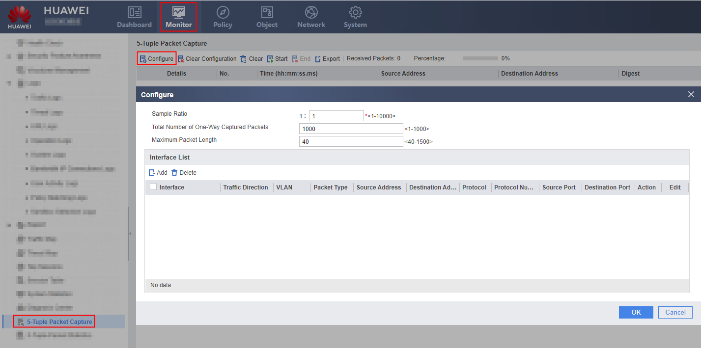
- Set global packet capture parameters.
Parameter
Description
Sample Ratio
Sampling ratio for packet capture. The value is an integer ranging from 1 to 10000. The default value is 1:1.
Total Number of One-Way Captured Packets
Maximum number of captured packets. The value ranges from 1 to 1000 and default value is 1000.
Maximum Packet Length
Maximum length of captured packets. The value is an integer ranging from 40 to 1500. The default value is 40.
- Configure packet capture on an interface.
- In Interface List, click Add, select an interface, and set Traffic Direction and Packet Type.
Parameter
Description
Interface
Interface for packet capture. A maximum of eight interfaces can be configured.
If ALL is selected, the incoming and outgoing packets of all interfaces are captured. If this parameter is set to ALL, you cannot specify an interface for packet capture. Global packet capture includes the packets of any specific interface.
Traffic Direction
Direction of packets to be captured:- Inbound: received packets.
- Outbound: sent packets.
VLAN
VLAN from which packets are to be captured.
This parameter is available only when Interface is set to a Layer-2 interface.
Packet Type
- IPv4 packet: captures IPv4 packets on the specified interface.
- Non-IP packet: captures non-IP packets on the specified interface. The FW can capture only ARP packets among all non-IP packets.
- All packet: captures IP and non-IP packets.
The web UI does not support the capture of IPv6 packets. The CLI supports the capture of IPv6 packets. For example, a user runs the command to capture IPv6 packets on GigabitEthernet 0/0/1 and the user clicks Add on the web UI to capture IPv4 packets on GigabitEthernet 0/0/1, a message similar to is displayed.
- Optional: Create ACL rules. In Rule List, click Add and set packet capture rules such as the source address, destination address, protocol, and action.
There are following limitations for rule creation:- Creating rules on an interface helps you accurately capture packets based on the rules. No rule can be created if the packet type is all or non-IP packets.. Therefore, only when the packet type is IPv4, rules can be created.
- If you have set the packet type to IPv4 on an interface and created one or more rules, you need to delete all rules and then select the packet type if you want to capture the packets of another type.
- A maximum of 10 rules can be configured for each interface on the web UI, and a maximum of 1000 rules can be configured on the CLI. If more than 10 rules are configured using the CLI, the web UI displays a message indicating that more than 10 rules have been configured. The web UI displays only the latest 10 rules.
- If multiple rules are configured, the system captures packets in sequence based on the configured rules.
- On the web UI, you can create a rule for capturing incoming and outgoing packets on an interface. However, you cannot configure an inbound rule for an interface and then an outbound rule for the same interface.
- On the web UI, you cannot configure packet capture for Down interfaces. The command can be used on the CLI but no packet can be captured. If you run this command on the CLI, the web UI displays a message, indicating that the interface is Down and does not support packet capture.
Parameter
Description
Source Address
Source IPv4 address of the packets to be captured.
This parameter is available only when Packet Type is IPv4.
Click the source address link to modify detailed information about the rule.
Destination Address
Destination IPv4 address of the packets to be captured.
This parameter is available only when Packet Type is IPv4.
Protocol
Protocol of the packets to be captured.
This parameter is available only when Packet Type is IPv4.
- In Interface List, click Add, select an interface, and set Traffic Direction and Packet Type.
- Click Start, set the packet capture sampling ratio in the dialog box displayed, read through the packet capture statement, and start capturing packets.
The FW captures a maximum of 1000 packets at a time. If the FW captures inbound and outbound packets at the same time, a maximum of 2000 packets can be captured. Therefore, the FW can receive a maximum of 2000 packets. However, the 5-Tuple Packet Capture interface displays only 1000 packets.
You can view Received Packets and Percentage on the web UI to have an overview on received packets. Received Packets indicates the number of received packets, and Percentage indicates the percentage of received packets in the total capacity (1000 packets).
Ensure that you enable packet capture in off-peak hours to prevent misoperations from interrupting services.

The value of Received Packets displays only Ethernet, 802.3, and 802.1Q packets at the data link layer.
- Optional: Click End to stop capturing packets.
If you do not click End and the number of captured packets reaches 2000, the FW automatically stops capturing packets. You can click Clear to reset packet statistics for the FW and capture packets again.
If a packet capture process is stopped and started again, previously captured packets are deleted.
Result
The following snapshot shows the information about captured packets in a period of time:

The fields are described as follows:
Field |
Meaning |
|---|---|
Details |
Click |
No. |
Packet sequence number |
Time |
Packet capture time, in hh:mm:ss.ms format. hh is the hour, mm the minute, ss the second, and ms the millisecond. |
Source Address |
Packet source IPv4 address |
Destination Address |
Packet destination IPv4 address |
Digest |
Brief packet information, including the packet protocol, source port, and destination port |
Length (Byte) |
Length of the packet |
