LDP-IGP Synchronization
Background
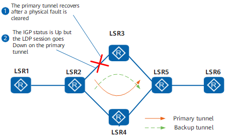
- When an active link fails, an IGP route of a standby link becomes reachable and a backup LSP over the standby link takes over traffic. After the active link recovers, the IGP route of the active link becomes reachable before an LDP session is established over the active link. As a result, traffic is dropped when being transmitted using the reachable IGP route along the unreachable LSP.
- When the IGP route of the active link is reachable and an LDP session between nodes on the active link fails, traffic is directed using the IGP route of the active link, whereas the LSP over the active link is torn down. Because a preferred IGP route of the standby link is unavailable, an LSP over the standby link cannot be established, causing traffic loss.
Related Concepts
LDP-IGP synchronization delays IGP route advertisement to ensure that the LDP session and IGP route converge simultaneously.
Status |
Status Description |
Timer |
Timer Description |
|---|---|---|---|
Init |
An interface configured with LDP-IGP synchronization goes Down. |
None |
- |
Hold-down |
An IGP does not send or receive Hello packets, which delays the establishment of an IGP neighbor relationship after the link recovers. |
Hold-down timer |
The Hold-down timer starts to count the period for delaying the establishment of the IGP neighbor relationship. If the value is set to 0, the Hold-down timer does not start. The default value is 10, in seconds. |
Hold-max-cost |
An IGP sets up an IGP neighbor relationship and advertises the maximum cost of the active link. |
Hold-max-cost timer |
The Hold-max-cost timer starts. Before it expires, an IGP keeps advertising the maximum link cost. If the value is set to 0, the Hold-max-cost timer does not start. The default value is 10, in seconds. |
Hold-normal-cos |
An IGP advertises the actual cost of the active link. |
None |
- |
Sync-achieved |
LDP-IGP synchronization is achieved. The LDP session is Up, an LSP is established, and the IGP advertises the actual cost of the active link. |
Delay timer |
The Delay timer starts after the LDP session goes Up. The Delay timer counts the period during which an LSP is being established. If the value is set to 0, the Delay timer does not start. The default value is 10, in seconds. |
Implementation
LDP-IGP synchronization state machine
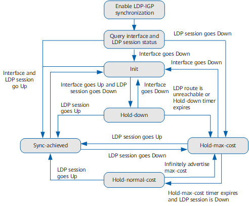
After LDP-IGP synchronization is enabled on an interface, the LDP-IGP synchronization state machine operates based on the flowchart shown in Figure 2. Note differences when different IGP protocols are used:
- When OSPF is used, the status transits based on the flowchart shown in Figure 2.
- When IS-IS is used, the Hold-normal-cost state does not exist. After the Hold-max-cost timer expires, IS-IS advertises the actual link cost, but the Hold-max-cost state is displayed even although this state is nonexistent.
State transition during LDP-IGP synchronization
Either of the following processes takes place based on Figure 1 and Figure 2.- The following process takes place after the physical fault is rectified on the active link:
The active link fails and the faulty interface enters the Init state.
The active link recovers and the interface goes Up.
The interface on LSR2 enters the Hold-down state. LSR2 and LSR3 establish an LDP session. The establishment of an IGP neighbor relationship is delayed. The Hold-down timer starts if the timer value is not 0.
Traffic keeps traveling through the LSP over the backup link.
The LDP session is established and an LSP is set up. The LDP module instructs the IGP module to start synchronization.
An IGP neighbor relationship starts to be established. An IGP route of the active link becomes reachable. An LSP is reestablished over the active link in milliseconds.
The Hold-down timer can be set. Using the default value is recommended.
- The following process takes place after the physical fault is rectified on the active link:
An LDP session between nodes on the active link fails.
The LDP module notifies the IGP module of the fault. The IGP interface enters the Hold-max-cost state. An IGP advertises the maximum cost of the active link and starts the Hold-max-cost timer.
The IGP route of the standby link becomes reachable.
An LSP is established over the standby link and the LDP module on LSR2 delivers forwarding entries.
The Hold-max-cost timer can be configured to always advertise the maximum cost of the active link. This setting allows traffic to keep traveling through the standby link before the LDP session over the active link is reestablished.
Other Functions
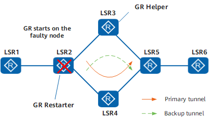
On the MPLS network shown in Figure 3, a graceful restart (GR) is performed after LSR2 goes faulty. The LDP session between LSR2 and LSR3 may be established after the GR is complete. If LDP-IGP synchronization is enabled on the interface between LSR2 and LSR3, LSR2 and LSR3 perform the following operations:
LSR2 functioning as a GR Restarter
During the GR process, an IGP advertises the actual cost of the active link and starts the GR Delay timer that delays the GR completion. The LDP session is waiting to be established before the GR is complete.
After the GR Delay timer expires, the GR is complete. If the LDP session is not established at this time, the IGP starts the Hold-max-cost timer and advertises the maximum active link cost of the interface, switching the IGP route to the standby link.
If the LDP session is reestablished or the Hold-max-cost timer expires, the IGP resumes the actual link cost of the interface, switching the IGP route back to the active link.
LSR3 functioning as a GR Helper
LSR3 retains the original IGP route and the LSP before the LDP GR is complete. When the LDP session goes Down, LDP does not notify the IGP link of the session Down event. In this case, the IGP still advertises the actual link cost, ensuring that the IGP route is not switched to the standby link.
If the LDP session is not established after the GR is complete, the IGP starts the Hold-max-cost timer and advertises the maximum active link cost of the interface, switching the IGP route to the standby link.
If the LDP session is reestablished or the Hold-max-cost timer expires, the IGP resumes the actual link cost of the interface, switching the IGP route back to the active link.