Example for Configuring Local LDP Sessions
This section describes how to configure local LDP sessions, including how to enable MPLS and LDP on nodes and interfaces.
Networking Requirements
As shown in Figure 1, LSRA, LSRB, and LSRC are core routers on an MPLS network. Before establishing an LSP to forward data traffic within the MPLS network, configure local LDP sessions between LSRA and LSRB, and LSRB and LSRC.
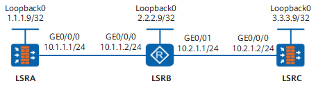
Configuration Roadmap
The configuration roadmap is as follows:
- Enable global MPLS and LDP on each LSR.
- Enable MPLS on interfaces of each LSR.
- Enable LDP on directly connected interfaces where local LDP sessions are to be established.
Procedure
- Configure IP addresses for interfaces.
# Configure LSRA. The configurations of LSRB and LSRC are similar to the configuration of LSRA, and are not mentioned here.
<sysname> system-view
[sysname] sysname LSRA
[LSRA] interface loopback 0
[LSRA-LoopBack0] ip address 1.1.1.9 32
[LSRA-LoopBack0] quit
[LSRA] interface GigabitEthernet 0/0/0
[LSRA-GigabitEthernet0/0/0] ip address 10.1.1.1 24
[LSRA-GigabitEthernet0/0/0] quit
- Assign interfaces of LSRA and LSRC to security zones and configure interzone security policies.
# Configure LSRA.
[LSRA] firewall zone untrust
[LSRA-zone-untrust] add interface GigabitEthernet 0/0/0
[LSRA-zone-untrust] quit
[LSRA] security-policy
[LSRA-policy-security] rule name policy_sec_1
[LSRA-policy-security-rule-policy_sec_1] source-zone local untrust
[LSRA-policy-security-rule-policy_sec_1] destination-zone untrust local
[LSRA-policy-security-rule-policy_sec_1] action permit
[LSRA-policy-security-rule-policy_sec_1] quit
[LSRA-policy-security] quit
# The configuration of LSRC is similar to the configuration of LSRA and is not mentioned here.
- Configure OSPF to advertise the network segments connecting to interfaces on each node and to advertise the routes of hosts with LSR IDs.
# Configure LSRA
[LSRA] ospf 1
[LSRA-ospf-1] area 0
[LSRA-ospf-1-area-0.0.0.0] network 1.1.1.9 0.0.0.0
[LSRA-ospf-1-area-0.0.0.0] network 10.1.1.0 0.0.0.255
[LSRA-ospf-1-area-0.0.0.0] quit
[LSRA-ospf-1] quit
# Configure LSRB
[LSRB] ospf 1
[LSRB-ospf-1] area 0
[LSRB-ospf-1-area-0.0.0.0] network 2.2.2.9 0.0.0.0
[LSRB-ospf-1-area-0.0.0.0] network 10.1.1.0 0.0.0.255
[LSRB-ospf-1-area-0.0.0.0] network 10.2.1.0 0.0.0.255
[LSRB-ospf-1-area-0.0.0.0] quit
[LSRB-ospf-1] quit
# Configure LSRC
[LSRC] ospf 1
[LSRC-ospf-1] area 0
[LSRC-ospf-1-area-0.0.0.0] network 3.3.3.9 0.0.0.0
[LSRC-ospf-1-area-0.0.0.0] network 10.2.1.0 0.0.0.255
[LSRC-ospf-1-area-0.0.0.0] quit
[LSRC-ospf-1] quit
# After the configuration is complete, run the display ip routing-table command on each node, and you can view that the nodes learn routes from each other.
- Enable global MPLS and MPLS LDP on each LSR.
# Configure LSRA.
[LSRA] mpls lsr-id 1.1.1.9
[LSRA] mpls
[LSRA-mpls] quit
[LSRA] mpls ldp
[LSRA-mpls-ldp] quit
# Configure LSRB.
[LSRB] mpls lsr-id 2.2.2.9
[LSRB] mpls
[LSRB-mpls] quit
[LSRB] mpls ldp
[LSRB-mpls-ldp] quit
# Configure LSRC.
[LSRC] mpls lsr-id 3.3.3.9
[LSRC] mpls
[LSRC-mpls] quit
[LSRC] mpls ldp
[LSRC-mpls-ldp] quit
- Enable MPLS and MPLS LDP on interfaces of each LSR.
# Configure LSRA.
[LSRA] interface GigabitEthernet 0/0/0
[LSRA-GigabitEthernet0/0/0] mpls
[LSRA-GigabitEthernet0/0/0] mpls ldp
[LSRA-GigabitEthernet0/0/0] quit
# Configure LSRB.
[LSRB] interface GigabitEthernet 0/0/0
[LSRB-GigabitEthernet0/0/0] mpls
[LSRB-GigabitEthernet0/0/0] mpls ldp
[LSRB-GigabitEthernet0/0/0] quit
[LSRB] interface GigabitEthernet 0/0/1
[LSRB-GigabitEthernet0/0/1] mpls
[LSRB-GigabitEthernet0/0/1] mpls ldp
[LSRB-GigabitEthernet0/0/1] quit
# Configure LSRC.
[LSRC] interface GigabitEthernet 0/0/0
[LSRC-GigabitEthernet0/0/0] mpls
[LSRC-GigabitEthernet0/0/0] mpls ldp
[LSRC-GigabitEthernet0/0/0] quit
- Verify the configuration.
# After the configuration is complete, run the display mpls ldp session command. The command output shows that the status of local LDP sessions between LSRA and LSRB and between LSRB and LSRC is Operational.
LSRA is used as an example.
[LSRA] display mpls ldp session

 LDP Session(s) in Public Network
 Codes: LAM(Label Advertisement Mode), SsnAge Unit(DDDD:HH:MM)
 A '*' before a session means the session is being deleted.
 ------------------------------------------------------------------------------
 PeerID             Status      LAM  SsnRole  SsnAge      KASent/Rcv
 ------------------------------------------------------------------------------
 2.2.2.9:0          Operational DU   Passive  0000:00:22   91/91
 ------------------------------------------------------------------------------
 TOTAL: 1 session(s) Found.
Configuration Scripts
Configuration script of LSRA
#
 sysname LSRA
#
 mpls lsr-id 1.1.1.9
 mpls
#
mpls ldp
#
interface GigabitEthernet0/0/0
 ip address 10.1.1.1 255.255.255.0
 mpls
 mpls ldp
#
interface LoopBack0
 ip address 1.1.1.9 255.255.255.255
#
firewall zone untrust
 set priority 5
 add interface GigabitEthernet0/0/0
#
security-policy
  rule name policy_sec_1
    source-zone local
    source-zone untrust
    destination-zone local
    destination-zone untrust
    action permit
#
ospf 1
 area 0.0.0.0
  network 1.1.1.9 0.0.0.0
  network 10.1.1.0 0.0.0.255
#
return
Configuration script of LSRB
#
 sysname LSRB
#
 mpls lsr-id 2.2.2.9
 mpls
#
mpls ldp
#
interface GigabitEthernet0/0/0
 ip address 10.1.1.2 255.255.255.0
 mpls
 mpls ldp
#
interface GigabitEthernet0/0/1
 ip address 10.2.1.1 255.255.255.0
 mpls
 mpls ldp
#
interface LoopBack0
 ip address 2.2.2.9 255.255.255.255
#
ospf 1
 area 0.0.0.0
  network 2.2.2.9 0.0.0.0
  network 10.1.1.0 0.0.0.255
  network 10.2.1.0 0.0.0.255
#
return
Configuration script of LSRC
#
 sysname LSRC
#
 mpls lsr-id 3.3.3.9
 mpls
#
mpls ldp
#
interface GigabitEthernet0/0/0
 ip address 10.2.1.2 255.255.255.0
 mpls
 mpls ldp
#
interface LoopBack0
 ip address 3.3.3.9 255.255.255.255
#
firewall zone untrust
 set priority 5
 add interface GigabitEthernet0/0/0
#
security-policy
  rule name policy_sec_1
    source-zone local
    source-zone untrust
    destination-zone local
    destination-zone untrust
    action permit
#
ospf 1
 area 0.0.0.0
  network 3.3.3.9 0.0.0.0
  network 10.2.1.0 0.0.0.255
#
return