Basic BGP/MPLS IP VPN
Definition
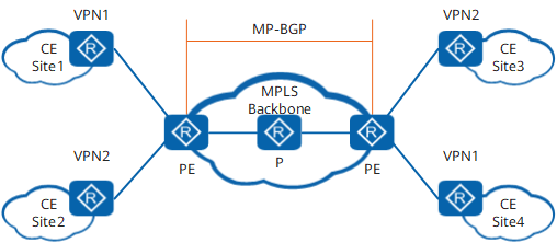
Transmits packets using extended BGP.
Encapsulates and transmits VPN packets over MPLS LSPs serving as public network tunnels.
Allows a device that can play PE, P, and CE roles to play only one role at a time.
Related Concepts
Site
The concept of "site" is frequently mentioned in the VPN technology. The following describes a site from different aspects:
A site is a group of IP systems with IP connectivity that can be achieved independent of service provider (SP) networks.
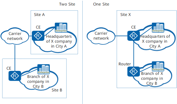
As shown in Figure 2, on the networks on the left, the headquarters of company X in city A is a site, the branch of company X in city B is another site. IP devices can communicate within each site without using the SP network.
Sites are classified based on the topological relationships between devices rather than the geographical locations of devices, although devices in a site are geographically adjacent to each other in general. If two geographically separated IP systems are connected over a leased line, the two systems form a site if they can communicate without the help of SP networks.
As shown in Figure 2, if the branch network in city B is connected to the headquarters network in city A over a leased line instead of an SP network, the branch network and the headquarters network form a site.
The devices at a site may belong to multiple VPNs. In other words, a site may belong to more than one VPN.
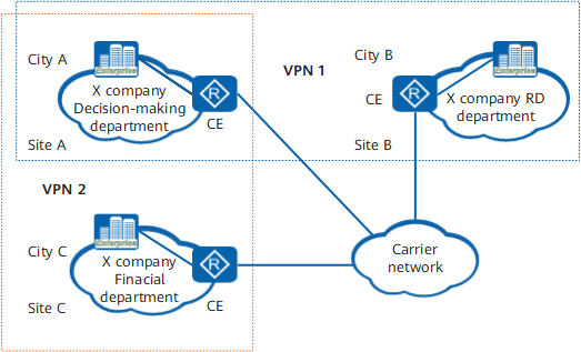
As shown in Figure 3, in company X, the decision-making department in city A (Site A) is allowed to communicate with the research and development (R&D) department in city B (Site B) and the financial department in city C (Site C). Site B and Site C are not allowed to communicate with each other. In this case, two VPNs (VPN1 and VPN2) can be established with Site A and Site B belonging to VPN1 and Site A and Site C belonging to VPN2. In this manner, Site A is configured to belong to multiple VPNs.
A site is connected to an SP network using a CE. A site may contain more than one CE, but a CE belongs to only one site.
It is recommended that you determine the devices to be used as CEs based on the following principles:
If the site is a host, use the host as the CE.
If the site is a subnet, use switches as CEs.
If the site comprises multiple subnets, use routers as CEs.
Sites connected to the same SP network can be classified into different sets based on configured policies. Only sites that belong to the same set can access each other, and this set is a VPN.
-
As a private network, a VPN independently manages an address space. Address spaces of different VPNs may overlap. For example, if both VPN1 and VPN2 use addresses on the network segment 10.110.10.0/24, address space overlapping occurs.

VPNs can use overlapped address spaces in the following situations:
Two VPNs do not cover the same site.
Two VPNs cover the same site, but devices at the site and devices using addresses in overlapped address spaces in the VPNs cannot access each other.
-
CEs are user-side devices and need to send only local VPN routes to PEs, irrespective of whether the PEs are connected to the public network or other VPNs. PEs are network-side devices, and a PE is generally connected to multiple CEs from different VPNs. A PE may receive routes from different VPNs. Because address spaces used by different VPNs may overlap, routes sent from different VPNs may carry the same destination address. If a PE maintains only one routing and forwarding table, this table will accept only one of the routes from different VPNs but with the same destination address. To prevent this problem, the VPN technology uses VPN instances.
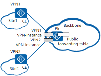
A VPN instance is also called a VPN routing and forwarding (VRF) table. A PE maintains multiple routing and forwarding tables, including a public routing and forwarding table and one or more VRFs. A PE has multiple instances, including a public network instance and one or more VPN instances, as shown in Figure 4. Each VPN instance maintains routes from the corresponding VPN. The public network instance maintains public network routes. This enables a PE to keep all routes from VPNs, irrespective of their address spaces overlap.
The differences between a public routing and forwarding table and a VRF are as follows:
A public routing table contains the IPv4 routes of all PEs and Ps. These IPv4 routes are static routes configured on the backbone network or are generated by routing protocols configured on the backbone network.
A VPN routing table contains the routes of all sites that belong to the corresponding VPN instance. The routes are obtained through exchange of VPN routes between PEs or between CEs and PEs.
According to route management policies, a public forwarding table contains the minimum forwarding information extracted from the corresponding routing table, whereas a VPN forwarding table contains the minimum forwarding information extracted from the corresponding VPN routing table.
VPN instances on a PE are independent of each other and of the public routing and forwarding table.
Each VPN instance can be regarded as a virtual router, which maintains an independent address space and has one or more interfaces connected to the router.
In RFC 4364 (BGP/MPLS IP VPNs), a VPN instance is called a per-site forwarding table. As the name suggests, one VPN instance corresponds to one site. To be more accurate, every connection between a CE and a PE corresponds to a VPN instance, but this is not a one-to-one mapping. The VPN instance is manually bound to the PE interface that directly connects to the CE.
A VPN instance uses a route distinguisher (RD) to identify an independent address space and uses VPN targets to manage VPN memberships and routing principles of directly connected sites and remote sites.
Relationships between VPNs, sites, and VPN instances
The relationships between VPNs, sites, and VPN instances are as follows:
A VPN consists of multiple sites. A site may belong to multiple VPNs.
A site is associated with a VPN instance on a PE. A VPN instance integrates the VPN member relationships and routing principles of its associated sites. Multiple sites form a VPN based on VPN instance rules.
-
Traditional BGP cannot process the routes that have overlapping address spaces. Assume that VPN1 and VPN2 use addresses on the network segment 10.110.10.0/24, and each of them advertises a route destined for this network segment. The local PE identifies the two VPN routes based on VPN instances and sends them to the remote PE. Because routes from different VPNs cannot work in load-balancing mode, the remote PE adds only one of the two routes to its VRF based on BGP route selection rules.
This is because BGP cannot distinguish VPN routes with the same IP address prefix. To solve this problem, BGP/MPLS IP VPN uses the VPN-IPv4 address family.
A VPN-IPv4 address consists of 12 bytes. The first eight bytes represent the RD and the last four bytes the IPv4 address prefix, as shown in Figure 5.
RDs are used to distinguish address spaces with the same IPv4 address prefix. The format of RDs enables SPs to allocate RDs independently. An RD, however, must be unique on the entire network to ensure correct routing if CEs are dual-homed to PEs. IPv4 addresses with RDs are called VPN-IPv4 addresses. After receiving IPv4 routes from a CE, a PE converts the routes to globally unique VPN-IPv4 routes and advertises the routes on the public network.
-
The VPN target, also called the route target (RT), is a 32-bit extended community attribute. BGP/MPLS IP VPN uses the VPN target to control the advertising of VPN routing information.
A VPN instance is associated with one or more VPN targets. VPN targets are classified into the following types:
Export target: After learning an IPv4 route from a directly connected site, a PE converts the route to a VPN-IPv4 route and sets export targets for the route. As an extended community attribute, export targets are advertised with the route.
Import target: After receiving a VPN-IPv4 route from one PE, a second PE checks the export targets of the route. If one of the export targets is identical with an import target of a VPN instance on the PE, the PE adds the route to the corresponding VRF.
A VPN target defines which sites can receive a VPN route and which VPN routes of which sites can be received by a PE.
After receiving a route from a directly connected CE, a PE sets export targets for the route. The PE then uses BGP to advertise the route with the export targets to related PEs. After receiving the route, the related PEs compare the export targets with the import targets of all their VPN instances. If an export target is identical with an import target, the route is added to the corresponding VRF.
The reasons for using the VPN target instead of the RD as the extended community attribute is as follows:
A VPN-IPv4 route has only one RD, but can be associated with multiple VPN targets. With multiple extended community attributes, BGP can greatly improve the flexibility and expansibility of a network.
VPN targets can be used to control route advertisement between different VPNs on a PE. With properly configured VPN targets, different VPN instances on a PE can import routes from each other.
On a PE, different VPNs have different RDs, but the extended community attributes allowed by BGP are limited. Using RDs for route importing limits network expansibility.
On a BGP/MPLS IP VPN, VPN targets can be used to control exchange of VPN routes between sites. Export targets and import targets are independent of each other and can be configured with multiple values, ensuring flexible VPN access control and diversified VPN networking modes.
-
Traditional BGP-4 defined in RFC 1771 can manage IPv4 routes but not the routes of VPNs with overlapped address spaces.
To correctly process VPN routes, VPNs use MP-BGP defined in RFC 2858 (Multiprotocol Extensions for BGP-4). MP-BGP supports multiple network layer protocols. Network layer protocol information is contained in the Network Layer Reachability Information (NLRI) field and the Next Hop field of an MP-BGP Update message.
MP-BGP uses the address family to differentiate network layer protocols. An address family can be a traditional IPv4 address family or any other address family, such as a VPN-IPv4 address family or an IPv6 address family. For the values of address families, see RFC 1700 (Assigned Numbers).

Route Advertisement on a Basic BGP/MPLS IP VPN
Advertisement from local CEs to the ingress PE
After neighbor or peer relationships are established between CEs and their directly connected PE, the CEs advertise local VPN routes to the PE. CEs can communicate with the PE over static routes or routes established using Routing Information Protocol (RIP), Open Shortest Path First (OSPF), Intermediate System-to-Intermediate System (IS-IS), or BGP. Regardless of which routing protocol is used, routes advertised by CEs to the PE are standard IPv4 routes.
VPN instances on a PE are isolated from each other and independent of the public routing and forwarding table, to prevent problems caused by address space overlapping. After learning routes from CEs, a PE decides to which routing and forwarding table the routes need to be added based on configurations. Common static routes and routing protocols do not have this capability, and manual configuration is required.
Advertisement from the ingress PE to the egress PE
Advertisement from the ingress PE to the egress PE consists of the following parts:
After learning VPN routes from a CE, a PE stores these routes in corresponding VRFs and adds RDs to these standard IPv4 routes, generating VPN-IPv4 routes.
The ingress PE advertises VPN-IPv4 routes to the egress PE by sending MP-BGP Update messages. The MP-BGP Update messages also contain VPN targets and MPLS labels.
Before being sent to the next-hop PE, these VPN-IPv4 routes are filtered by BGP routing policies, including the VRF export policy and peer export policy.
After these routes arrive at the egress PE, if they pass the peer import policy and their next hops are reachable or they can be iterated, the egress PE performs local route crossing and filters these routes based on a VRF import policy. The egress PE then decides which routes are to be added to its VRFs. Routes received from other PEs are added to the VPN routing table based on VPN targets. The egress PE stores the following information for subsequent packet forwarding:
Values of MPLS labels contained in MP-BGP Update messages
Tunnel IDs generated after tunnel iteration
Advertisement from the egress PE to remote CEs
A remote CE can learn VPN routes from an egress PE over static routes or routes established using RIP, OSPF, IS-IS, and BGP. Route advertisement from the egress PE to a remote CE is similar to that from a local CE to the ingress PE. The details are not described here. Note that routes advertised by the egress PE to a remote CE are standard IPv4 routes.
After a PE receives routes of different VPNs from a local CE, if the next hops of these routes are reachable or these routes can be iterated, the PE matches the export targets of these routes with its VRF import targets. This process is called local route crossing. During local route crossing, the PE filters these routes based on a VRF import policy and modifies the attributes of eligible routes.
Packet Forwarding on a BGP/MPLS IP VPN
On a BGP/MPLS IP VPN backbone network, Ps cannot recognize VPN routing information, so VPN packets are forwarded between PEs over tunnels. Figure 6 shows an example of packet forwarding on a BGP/MPLS IP VPN. A packet is transmitted from CE1 to CE2. I-L indicates an inner label, and O-L indicates an outer label. The outer label directs the packet to the BGP next hop, and the inner label identifies the outbound interface for the packet or the VPN to which the packet belongs.
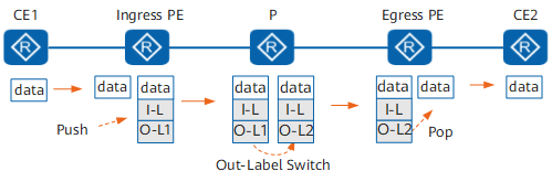
- CE1 sends a VPN packet to the ingress PE.
- After receiving the packet from an interface bound to a VPN instance, the ingress PE performs the following steps:
- Searches the corresponding VPN forwarding table based on the RD of the bound VPN instance.
- Matches the destination IPv4 address with forwarding entries and searches for the corresponding tunnel ID.
- Adds an I-L to the packet and finds the tunnel to be used based on the tunnel ID.
- Adds an outer label to the packet and sends the packet over the tunnel. In this example, the tunnel is an LSP, and the outer label is an MPLS label.
- Transmits the double-tagged packet over the backbone network. Each P on the forwarding path swaps the outer label of the packet.
- After receiving the packet, the egress PE removes the outer label of the packet.
In this example, the final outer label of the packet is O-L2. If penultimate hop popping (PHP) is configured, O-L2 is removed on the penultimate hop, and the egress PE receives a packet with the inner label only.
- The egress PE removes the inner label residing at the bottom of the label stack.
- The egress PE sends the packet from the corresponding outbound interface to CE2. After its labels are removed, the packet becomes a pure IP packet.
In this manner, the packet is sent from CE1 to CE2. CE2 forwards the packet to the destination in the way it sends other IP packets.
Benefits
- Enables users to communicate with each other over networks of geographically different regions.
- Ensures the security of VPN data during transmission on the public network.