Example for Configuring BGP/MPLS IP VPN Users to Access the Internet Through NAT
This section describes how to configure BGP/MPLS IP VPN and how to configure VPN users to access the Internet through NAT.
Networking Requirements
CE1 and CE2 belong to VPNA.
VPN users can communicate.
VPN users access the Internet through the public interface of PE2.
- The private addresses of users are translated into public addresses during the access to the Internet.
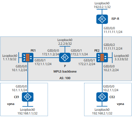
Configuration Roadmap
In this example, the ISP-R simulate the public network router at the ISP side, the loopback interfaces of the CE and ISP-R simulate VPN users and public network devices. The configuration roadmap is as follows:
- Configure basic BGP/MPLS VPN functions.
Configure OSPF on the backbone network to enable PEs to communicate.
Configure basic MPLS functions and MPLS LDP and establish MPLS LSPs.
Configure MP-IBGP on the PEs to exchange VPN routing information.
Configure VPN instances on the PEs and bind the PE interfaces connected to the CEs to corresponding VPN instances.
Configure OSPF on the CEs and PEs to exchange VPN routing information.
Configure VPN OSPF and BGP to import routes from each other.
- Configure a public network interface and NAT.
- Configure a public network interface on PE2 and access the VPN.
- Configure a default route and deliver it to VPN users through dynamic routes.
- Configure NAT on PE2.

Use the ping command to test the connectivity. Run the undo service-manage enable command on each PE interface. Otherwise, ping packets are discarded. After the connectivity test succeeds, run the service-manage enable command to enhance system security.
- If the FW is used to simulate a P device, run the undo firewall session link-state check command. Otherwise, MPLS packets are discarded. The last-hop P device will remove the MPLS header in advance, causing inconsistent forward and return packets.
- The following example provides basic security policy parameters. You can set other parameters to the desired values.
Data Planning
Besides the interfaces and IP addresses marked in the network diagram, you need to plan:
MPLS LSR-ID of each PE and P: loopback interface address
RD of VPNA: 100:1
- VPN-Target: 111:1
Address pool: 11.11.11.10 to 11.11.11.20
Procedure
- Configure OSPF on the MPLS backbone network for interworking between the PEs and P device.
# Configure PE1.
<FW> system-view
[FW] sysname PE1
[PE1] interface loopback 0
[PE1-LoopBack0] ip address 1.1.1.9 32
[PE1-LoopBack0] quit
[PE1] interface GigabitEthernet 0/0/1
[PE1-GigabitEthernet0/0/1] ip address 172.1.1.1 24
[PE1-GigabitEthernet0/0/1] quit
[PE1] firewall zone trust
[PE1-zone-trust] add interface GigabitEthernet 0/0/1
[PE1-zone-trust] quit
[PE1] ospf
[PE1-ospf-1] area 0
[PE1-ospf-1-area-0.0.0.0] network 172.1.1.0 0.0.0.255
[PE1-ospf-1-area-0.0.0.0] network 1.1.1.9 0.0.0.0
[PE1-ospf-1-area-0.0.0.0] quit
[PE1-ospf-1] quit
# Configure a security policy on PE1 to ensure the connectivity on the backbone network.
[PE1] security-policy
[PE1-policy-security] rule name policy_sec_1
[PE1-policy-security-rule-policy_sec_1] source-zone trust local
[PE1-policy-security-rule-policy_sec_1] destination-zone trust local
[PE1-policy-security-rule-policy_sec_1] action permit
[PE1-policy-security-rule-policy_sec_1] quit
# Configure the P device.
<Router> system-view
[Router] sysname P
[P] interface loopback 0
[P-LoopBack0] ip address 2.2.2.9 32
[P-LoopBack0] quit
[P] interface GigabitEthernet 0/0/0
[P-GigabitEthernet0/0/0] ip address 172.1.1.2 24
[P-GigabitEthernet0/0/0] quit
[P] interface GigabitEthernet 0/0/1
[P-GigabitEthernet0/0/1] ip address 172.2.1.1 24
[P-GigabitEthernet0/0/1] quit
[P] ospf 1
[P-ospf-1] area 0
[P-ospf-1-area-0.0.0.0] network 172.1.1.0 0.0.0.255
[P-ospf-1-area-0.0.0.0] network 172.2.1.0 0.0.0.255
[P-ospf-1-area-0.0.0.0] network 2.2.2.9 0.0.0.0
[P-ospf-1-area-0.0.0.0] quit
[P-ospf-1] quit
# Configure PE2.
<FW> system-view
[FW] sysname PE2
[PE2] interface loopback 0
[PE2-LoopBack0] ip address 3.3.3.9 32
[PE2-LoopBack0] quit
[PE2] interface GigabitEthernet 0/0/1
[PE2-GigabitEthernet0/0/1] ip address 172.2.1.2 24
[PE2-GigabitEthernet0/0/1] quit
[PE2] firewall zone trust
[PE2-zone-trust] add interface GigabitEthernet 0/0/1
[PE2-zone-trust] quit
[PE2] ospf 1
[PE2-ospf-1] area 0
[PE2-ospf-1-area-0.0.0.0] network 172.2.1.0 0.0.0.255
[PE2-ospf-1-area-0.0.0.0] network 3.3.3.9 0.0.0.0
[PE2-ospf-1-area-0.0.0.0] quit
[PE2-ospf-1] quit
# Configure a security policy on PE2 to ensure the connectivity on the backbone network.
[PE2] security-policy
[PE2-policy-security] rule name policy_sec_1
[PE2-policy-security-rule-policy_sec_1] source-zone trust local
[PE2-policy-security-rule-policy_sec_1] destination-zone trust local
[PE2-policy-security-rule-policy_sec_1] action permit
[PE2-policy-security-rule-policy_sec_1] quit
After the configurations are complete, OSPF neighbor relationships can be set up between PE1, the P device, and PE2. Run the display ospf peer command. The command output shows that the neighbor status is Full. Run the display ip routing-table command. The command output shows that PEs have learned the routes to Loopback1 from each other.
The following example uses the command output on PE1:
[PE1] display ip routing-table
Route Flags: R - relay, D - download to fib
------------------------------------------------------------------------------
Routing Tables: Public
         Destinations : 8       Routes : 8
Destination/Mask  Proto  Pre  Cost             Flags NextHop         Interface
      1.1.1.9/32  Direct 0    0                D  127.0.0.1       LoopBack1
      2.2.2.9/32 OSPF   10   1                D  172.1.1.2       GigabitEthernet0/0/1
      3.3.3.9/32 OSPF   10   2                D  172.1.1.2       GigabitEthernet0/0/1
    127.0.0.0/8   Direct 0    0                D  127.0.0.1       InLoopBack0
    127.0.0.1/32  Direct 0    0                D  127.0.0.1       InLoopBack0
    172.1.1.0/24  Direct 0    0                D  172.1.1.1       GigabitEthernet0/0/1
    172.1.1.1/32  Direct 0    0                D  127.0.0.1       GigabitEthernet0/0/1
    172.2.1.0/24  OSPF   10   2                D  172.1.1.2       GigabitEthernet0/0/1
[PE1] display ospf peer OSPF Process 1 with Router ID 1.1.1.9 Neighbors Area 0.0.0.0 interface 172.1.1.1(GigabitEthernet0/0/2)'s neighbors Router ID: 172.1.1.2 Address: 172.1.1.2 State: Full Mode:Nbr is Master Priority: 1 DR: None BDR: None MTU: 1500 Dead timer due in 38 sec Neighbor is up for 00:02:44 Authentication Sequence: [ 0 ] - On the MPLS backbone network, configure basic MPLS capabilities and MPLS LDPs and set up LDP LSPs.
# Configure PE1.
[PE1] mpls lsr-id 1.1.1.9
[PE1] mpls
[PE1-mpls] quit
[PE1] mpls ldp
[PE1-mpls-ldp] quit
[PE1] interface GigabitEthernet 0/0/1
[PE1-GigabitEthernet0/0/1] mpls
[PE1-GigabitEthernet0/0/1] mpls ldp
[PE1-GigabitEthernet0/0/1] quit
# Configure the P device.
[P] mpls lsr-id 2.2.2.9
[P] mpls
[P-mpls] quit
[P] mpls ldp
[P-mpls-ldp] quit
[P] interface GigabitEthernet 0/0/0
[P-GigabitEthernet0/0/0] mpls
[P-GigabitEthernet0/0/0] mpls ldp
[P-GigabitEthernet0/0/0] quit
[P] interface GigabitEthernet 0/0/1
[P-GigabitEthernet0/0/1] mpls
[P-GigabitEthernet0/0/1] mpls ldp
[P-GigabitEthernet0/0/1] quit
# Configure PE2.
[PE2] mpls lsr-id 3.3.3.9
[PE2] mpls
[PE2-mpls] quit
[PE2] mpls ldp
[PE2-mpls-ldp] quit
[PE2] interface GigabitEthernet 0/0/1
[PE2-GigabitEthernet0/0/1] mpls
[PE2-GigabitEthernet0/0/1] mpls ldp
[PE2-GigabitEthernet0/0/1] quit
After the configurations are complete, an LDP session is established between PE1 and the P device and between the P device and PE2. The display mpls ldp session command output shows that the Status field is Operational. Run the display mpls ldp lsp command. The command output shows LDP LSP configurations.
The following example uses the command output on PE1:
[PE1] display mpls ldp session
 LDP Session(s) in Public Network
 Codes: LAM(Label Advertisement Mode), SsnAge Unit(DDDD:HH:MM)
 A '*' before a session means the session is being deleted.
 ------------------------------------------------------------------------------
 PeerID             Status      LAM  SsnRole  SsnAge      KASent/Rcv
 ------------------------------------------------------------------------------
 2.2.2.9:0          Operational DU   Passive  0000:00:15  64/64
 3.3.3.9:0          Operational DU   Passive  0000:00:15  64/64
 ------------------------------------------------------------------------------
 TOTAL: 2 session(s) Found.
[PE1] display mpls ldp lsp
  LDP LSP Information
 -------------------------------------------------------------------------------
 DestAddress/Mask   In/OutLabel    UpstreamPeer    NextHop         OutInterface
 -------------------------------------------------------------------------------
 1.1.1.9/32         3/NULL         2.2.2.9         127.0.0.1       InLoop0
 1.1.1.9/32         3/NULL         3.3.3.9         127.0.0.1       InLoop0
*1.1.1.9/32         Liberal/1029                   DS/2.2.2.9
*1.1.1.9/32         Liberal/1031                   DS/3.3.3.9
 2.2.2.9/32         NULL/3         -               172.1.1.2       GE0/0/1
 2.2.2.9/32         1031/3         2.2.2.9         172.1.1.2       GE0/0/1
 2.2.2.9/32         1031/3         3.3.3.9         172.1.1.2       GE0/0/1
*2.2.2.9/32         Liberal/1030                   DS/3.3.3.9
 3.3.3.9/32         NULL/1028      -               172.1.1.2       GE0/0/1
 3.3.3.9/32         1032/1028      2.2.2.9         172.1.1.2       GE0/0/1
 3.3.3.9/32         1032/1028      3.3.3.9         172.1.1.2       GE0/0/1
*3.3.3.9/32         Liberal/3                      DS/3.3.3.9
 -------------------------------------------------------------------------------
 TOTAL: 8 Normal LSP(s) Found.
 TOTAL: 4 Liberal LSP(s) Found.
 TOTAL: 0 Frr LSP(s) Found.
 A '*' before an LSP means the LSP is not established
 A '*' before a Label means the USCB or DSCB is stale
 A '*' before a UpstreamPeer means the session is stale
 A '*' before a DS means the session is stale
 A '*' before a NextHop means the LSP is FRR LSP
- Establish an MP-IBGP peer relationship between the PEs.
# Configure PE1.
[PE1] bgp 100
[PE1-bgp] peer 3.3.3.9 as-number 100
[PE1-bgp] peer 3.3.3.9 connect-interface loopback 0
[PE1-bgp] ipv4-family vpnv4
[PE1-bgp-af-vpnv4] peer 3.3.3.9 enable
[PE1-bgp-af-vpnv4] quit
[PE1-bgp] quit
# Configure PE2.
[PE2] bgp 100
[PE2-bgp] peer 1.1.1.9 as-number 100
[PE2-bgp] peer 1.1.1.9 connect-interface loopback 0
[PE2-bgp] ipv4-family vpnv4
[PE2-bgp-af-vpnv4] peer 1.1.1.9 enable
[PE2-bgp-af-vpnv4] quit
[PE2-bgp] quit
After the configurations are complete, run the display bgp peer or display bgp vpnv4 all peer command on each PE. The command output shows that the MP-IBGP peer relationship between the PEs is in the Established state.
[PE1] display bgp vpnv4 all peer
BGP local router ID : 1.1.1.9
 Local AS number : 100
 Total number of peers : 1                 Peers in established state : 1
  Peer            V    AS  MsgRcvd  MsgSent    OutQ  Up/Down    State        PrefRcv

  3.3.3.9         4   100   12      18         0     00:09:38   Established  0
- Configure VPN instances on the PEs, connect the CEs to the PEs, and configure OSPF to exchange private routes.
# Configure a VPN instance and OSPF on PE1.
[PE1] ip vpn-instance vpna
[PE1-vpn-instance-vpna] ipv4-family
[PE1-vpn-instance-vpna-af-ipv4] route-distinguisher 100:1
[PE1-vpn-instance-vpna-af-ipv4] vpn-target 111:1 both
[PE1-vpn-instance-vpna-af-ipv4] quit
[PE1-vpn-instance-vpna] quit
[PE1] interface GigabitEthernet 0/0/0
[PE1-GigabitEthernet0/0/0] ip binding vpn-instance vpna
[PE1-GigabitEthernet0/0/0] ip address 10.1.1.2 24
[PE1-GigabitEthernet0/0/0] quit
[PE1] firewall zone dmz
[PE1-zone-dmz] add interface GigabitEthernet 0/0/0
[PE1-zone-dmz] quit
[PE1] ospf 100 vpn-instance vpna
[PE1-ospf-100] area 0
[PE1-ospf-100-area-0.0.0.0] network 10.1.1.2 0.0.0.255
[PE1-ospf-100-area-0.0.0.0] quit
# Configure a security policy on PE1 to ensure the connectivity between the CEs and between the CEs and PEs.
[PE1] security-policy
[PE1-policy-security] rule name policy_sec_2
[PE1-policy-security-rule-policy_sec_2] source-zone dmz local
[PE1-policy-security-rule-policy_sec_2] destination-zone dmz local
[PE1-policy-security-rule-policy_sec_2] action permit
[PE1-policy-security-rule-policy_sec_2] quit
[PE1-policy-security] rule name policy_sec_3
[PE1-policy-security-rule-policy_sec_3] source-zone dmz trust
[PE1-policy-security-rule-policy_sec_3] destination-zone dmz trust
[PE1-policy-security-rule-policy_sec_3] action permit
[PE1-policy-security-rule-policy_sec_3] quit
# Configure a VPN instance and OSPF on PE2.
[PE2] ip vpn-instance vpna
[PE2-vpn-instance-vpna] ipv4-family
[PE2-vpn-instance-vpna-af-ipv4] route-distinguisher 100:1
[PE2-vpn-instance-vpna-af-ipv4] vpn-target 111:1 both
[PE2-vpn-instance-vpna-af-ipv4] quit
[PE2-vpn-instance-vpna] quit
[PE2] interface GigabitEthernet 0/0/0
[PE2-GigabitEthernet0/0/0] ip binding vpn-instance vpna
[PE2-GigabitEthernet0/0/0] ip address 10.2.1.2 24
[PE2-GigabitEthernet0/0/0] quit
[PE2] firewall zone dmz
[PE2-zone-dmz] add interface GigabitEthernet 0/0/0
[PE2-zone-dmz] quit
[PE2] ospf 100 vpn-instance vpna
[PE2-ospf-100] area 0
[PE2-ospf-100-area-0.0.0.0] network 10.2.1.2 0.0.0.255
[PE2-ospf-100-area-0.0.0.0] quit
# Configure a security policy on PE2 to ensure the connectivity between the CEs and between the CEs and PEs.
[PE2] security-policy
[PE2-policy-security] rule name policy_sec_2
[PE2-policy-security-rule-policy_sec_2] source-zone dmz local
[PE2-policy-security-rule-policy_sec_2] destination-zone dmz local
[PE2-policy-security-rule-policy_sec_2] action permit
[PE2-policy-security-rule-policy_sec_2] quit
[PE2-policy-security] rule name policy_sec_3
[PE2-policy-security-rule-policy_sec_3] source-zone dmz trust
[PE2-policy-security-rule-policy_sec_3] destination-zone dmz trust
[PE2-policy-security-rule-policy_sec_3] action permit
[PE2-policy-security-rule-policy_sec_3] quit
# Configure CE1.
<Router> system-view
[Router] sysname CE1
[CE1] interface loopback 0
[CE1-LoopBack0] ip address 192.168.1.1 32
[CE1-LoopBack0] quit
[CE1] interface GigabitEthernet 0/0/0
[CE1-GigabitEthernet0/0/0] ip address 10.1.1.1 24
[CE1-GigabitEthernet0/0/0] quit
[CE1] ospf 1
[CE1-ospf-1] area 0
[CE1-ospf-1-area-0.0.0.0] network 10.1.1.1 0.0.0.255
[CE1-ospf-1-area-0.0.0.0] network 192.168.1.1 0.0.0.0
[CE1-ospf-1-area-0.0.0.0] quit
[CE1-ospf-1] quit
# Configure CE2.
<Router> system-view
[Router] sysname CE2
[CE2] interface loopback 0
[CE2-LoopBack0] ip address 192.168.2.1 32
[CE2-LoopBack0] quit
[CE2] interface GigabitEthernet 0/0/0
[CE2-GigabitEthernet0/0/0] ip address 10.2.1.1 24
[CE2-GigabitEthernet0/0/0] quit
[CE2] ospf 1
[CE2-ospf-1] area 0
[CE2-ospf-1-area-0.0.0.0] network 10.2.1.1 0.0.0.255
[CE2-ospf-1-area-0.0.0.0] network 192.168.2.1 0.0.0.0
[CE2-ospf-1-area-0.0.0.0] quit
[CE2-ospf-1] quit
After the configurations are complete, run the display ip vpn-instance verbose command to view the configuration status of the VPN instances. Each PE can successfully ping through the connected CE.
If multiple interfaces on a PE are bound to the same VPN instance, you need to specify -a source-ip-address in the ping -vpn-instance vpn-instance-name -a source-ip-address dest-ip-address command to ping the CE connected to the peer PE. Otherwise, the ping operation fails.
The following example uses the command output on PE1 and CE1:
[PE1] display ip vpn-instance verbose
 Total VPN-Instances configured : 1
 Total IPv4 VPN-Instances configured : 1
 Total IPv6 VPN-Instances configured : 0

 VPN-Instance Name and ID : vpna, 1
  Interfaces : GigabitEthernet0/0/0
 Address family ipv4
  Create date : 2009/01/21 11:30:35
  Up time : 0 days, 00 hours, 05 minutes and 19 seconds
  Route Distinguisher : 100:1
  Export VPN Targets :  111:1
  Import VPN Targets :  111:1
  Label Policy : label per route
  The diffserv-mode Information is : uniform
  The ttl-mode Information is : pipe
  Log Interval : 5
[PE1] ping -vpn-instance vpna 10.1.1.1 PING 10.1.1.1: 56 data bytes, press CTRL_C to break Reply from 10.1.1.1: bytes=56 Sequence=1 ttl=255 time=56 ms Reply from 10.1.1.1: bytes=56 Sequence=2 ttl=255 time=4 ms Reply from 10.1.1.1: bytes=56 Sequence=3 ttl=255 time=4 ms Reply from 10.1.1.1: bytes=56 Sequence=4 ttl=255 time=52 ms Reply from 10.1.1.1: bytes=56 Sequence=5 ttl=255 time=3 ms --- 10.1.1.1 ping statistics --- 5 packet(s) transmitted 5 packet(s) received 0.00% packet loss round-trip min/avg/max = 3/23/56 ms - Configure VPN OSPF and BGP to import routes from each other.
# On PE1, configure VPN OSPF and BGP to import routes from each other.
[PE1] bgp 100
[PE1-bgp] ipv4-family vpn-instance vpna
[PE1-bgp-vpna] import-route ospf 100
[PE1-bgp-vpna] quit
[PE1-bgp] quit
[PE1] ospf 100
[PE1-ospf-100] import-route bgp permit-ibgp
[PE1-ospf-100] quit
# On PE2, configure VPN OSPF and BGP to import routes from each other.
[PE2] bgp 100
[PE2-bgp] ipv4-family vpn-instance vpna
[PE2-bgp-vpna] import-route ospf 100
[PE2-bgp-vpna] quit
[PE2-bgp] quit
[PE2] ospf 100
[PE2-ospf-100] import-route bgp permit-ibgp
[PE2-ospf-100] quit
- Check the BGP/MPLS VPN configuration.
Run the display ip routing-table vpn-instance command on the PEs to view the routes to their connected CEs.
The following example uses the command output on PE1:
[PE1] display ip routing-table vpn-instance vpna
Route Flags: R - relay, D - download to fib
------------------------------------------------------------------------------
Routing Tables: vpna
         Destinations : 6        Routes : 6

Destination/Mask    Proto   Pre  Cost      Flags NextHop         Interface

       10.1.1.0/24  Direct  0    0           D   10.1.1.2        GigabitEthernet 0/0/0
       10.1.1.2/32  Direct  0    0           D   127.0.0.1       GigabitEthernet 0/0/0
       10.2.1.0/24  IBGP    255  0          RD   3.3.3.9         GigabitEthernet 0/0/1
    192.168.1.1/32  OSPF    10   1           D   10.1.1.1        GigabitEthernet 0/0/0
    192.168.2.1/32  IBGP    255  2          RD   3.3.3.9         GigabitEthernet 0/0/1
The CEs on the same VPN can ping each other. The loopback 0 address of CE1 can ping the loopback 0 address of CE2.
<CE1> ping -a 192.168.1.1 192.168.2.1 PING 192.168.2.1: 56 data bytes, press CTRL_C to break Reply from 192.168.2.1: bytes=56 Sequence=1 ttl=252 time=4 ms Reply from 192.168.2.1: bytes=56 Sequence=2 ttl=252 time=2 ms Reply from 192.168.2.1: bytes=56 Sequence=3 ttl=252 time=2 ms Reply from 192.168.2.1: bytes=56 Sequence=4 ttl=252 time=3 ms Reply from 192.168.2.1: bytes=56 Sequence=5 ttl=252 time=2 ms --- 192.168.2.1 ping statistics --- 5 packet(s) transmitted 5 packet(s) received 0.00% packet loss round-trip min/avg/max = 2/2/4 ms - Configure a public network interface on PE2 and access the VPN.
[PE2] interface GigabitEthernet 0/0/2
[PE2-GigabitEthernet0/0/2] ip binding vpn-instance vpna
[PE2-GigabitEthernet0/0/2] ip address 11.11.11.2 24
[PE2-GigabitEthernet0/0/2] quit
[PE2] firewall zone untrust
[PE2-zone-untrust] add interface GigabitEthernet 0/0/2
[PE2-zone-untrust] quit
# Configure a security policy to allow VPN users to access the Internet.
[PE2-policy-security] rule name policy_sec_4
[PE2-policy-security-rule-policy_sec_4] source-zone dmz trust
[PE2-policy-security-rule-policy_sec_4] destination-zone untrust
[PE2-policy-security-rule-policy_sec_4] action permit
[PE2-policy-security-rule-policy_sec_4] quit
# Configure an interface address on the ISP-R. The configuration details are not provided.
- Configure a default route and deliver it to VPN users through dynamic routes.
# Configure a default route on PE2 and import it to BGP and OSPF.
[PE2] ip route-static vpn-instance vpna 0.0.0.0 0.0.0.0 11.11.11.1
[PE2] bgp 100
[PE2-bgp] ipv4-family vpn-instance vpna
[PE2-bgp-vpna] default-route imported
[PE2-bgp-vpna] import-route static
[PE2-bgp-vpna] quit
[PE2-bgp] quit
[PE2] ospf 100
[PE2-ospf-100] default-route-advertise
[PE2-ospf-100] quit
# On PE1, import the configured default route to OSPF.
[PE1] ospf 100
[PE1-ospf-100] default-route-advertise
[PE1-ospf-100] quit
# Run the display ip routing-table command on CE1 and CE2. The command output shows that VPN users receive the default routes.
[CE1] display ip routing-table vpn-instance Route Flags: R - relay, D - download to fib ------------------------------------------------------------------------------ Routing Tables: Public Destinations : 11 Routes : 11 Destination/Mask Proto Pre Cost Flags NextHop Interface 0.0.0.0/0 O_ASE 150 1 D 10.1.1.2 GigabitEthernet 0/0/0 10.1.1.0/24 Direct 0 0 D 10.1.1.1 GigabitEthernet 0/0/0 10.1.1.1/32 Direct 0 0 D 127.0.0.1 GigabitEthernet 0/0/0 10.2.1.0/24 O_ASE 150 1 D 10.1.1.2 GigabitEthernet 0/0/0 127.0.0.0/8 Direct 0 0 D 127.0.0.1 InLoopBack0 127.0.0.1/32 Direct 0 0 D 127.0.0.1 InLoopBack0 192.168.1.1/32 Direct 0 0 D 127.0.0.1 LoopBack0 192.168.2.1/32 OSPF 10 3 D 10.1.1.2 GigabitEthernet 0/0/0 - Configure NAT.
[PE2] nat address-group vpna
[PE2-address-group-vpna] mode full-cone global
[PE2-address-group-vpna] section 0 11.11.11.10 11.11.11.20
[PE2-address-group-vpna] quit
[PE2] nat-policy
[PE2-policy-nat] rule name vpna
[PE2-policy-nat-rule-vpna] source-zone trust dmz
[PE2-policy-nat-rule-vpna] source-address 192.168.0.0 16
[PE2-policy-nat-rule-vpna] destination-zone untrust
[PE2-policy-nat-rule-vpna] action source-nat address-group vpna
[PE2-policy-nat-rule-vpna] quit
[PE2-policy-nat] quit
- Check whether VPN users can access the Internet.
# On CE1 and CE2, configure the loopback interface to ping the loopback interface of the ISP-R. The ping operation succeeds.
[CE1] ping -a 192.168.1.1 192.0.2.1
  PING 192.0.2.1: 56  data bytes, press CTRL_C to break
    Reply from 192.0.2.1: bytes=56 Sequence=1 ttl=252 time=2 ms
    Reply from 192.0.2.1: bytes=56 Sequence=2 ttl=252 time=2 ms
    Reply from 192.0.2.1: bytes=56 Sequence=3 ttl=252 time=2 ms
    Reply from 192.0.2.1: bytes=56 Sequence=4 ttl=252 time=2 ms
    Reply from 192.0.2.1: bytes=56 Sequence=5 ttl=252 time=2 ms

  --- 192.0.2.1 ping statistics ---
    5 packet(s) transmitted
    5 packet(s) received
    0.00% packet loss
    round-trip min/avg/max = 2/2/2 ms
[CE2] ping -a 192.168.2.1 192.0.2.1 PING 192.0.2.1: 56 data bytes, press CTRL_C to break Reply from 192.0.2.1: bytes=56 Sequence=1 ttl=252 time=2 ms Reply from 192.0.2.1: bytes=56 Sequence=2 ttl=252 time=2 ms Reply from 192.0.2.1: bytes=56 Sequence=3 ttl=252 time=2 ms Reply from 192.0.2.1: bytes=56 Sequence=4 ttl=252 time=2 ms Reply from 192.0.2.1: bytes=56 Sequence=5 ttl=252 time=2 ms --- 192.0.2.1 ping statistics --- 5 packet(s) transmitted 5 packet(s) received 0.00% packet loss round-trip min/avg/max = 2/2/2 ms# On PE2, run the display firewall session table destination global command to check whether address translation succeeds.[PE2] display firewall session table destination global 192.0.2.1 2017-02-28 21:52:50.370 Current Total Sessions : 2 icmp VPN: vpna --> vpna 192.168.2.1:55211[11.11.11.19:55296] --> 192.0.2.1:2048 icmp VPN: vpna --> vpna 192.168.1.1:56747[11.11.11.20:6144] --> 192.0.2.1:2048
Configuration Scripts
Configuration script of PE1
#
sysname PE1
#
ip vpn-instance vpna
ipv4-family
route-distinguisher 100:1
vpn-target 111:1 export-extcommunity
vpn-target 111:1 import-extcommunity
#
mpls lsr-id 1.1.1.9
mpls
#
mpls ldp
#
interface GigabitEthernet0/0/0ip binding vpn-instance vpna
ip address 10.1.1.2 255.255.255.0
#
interface GigabitEthernet0/0/1ip address 172.1.1.1 255.255.255.0
mpls
mpls ldp
#
interface LoopBack0
ip address 1.1.1.9 255.255.255.255
#
firewall zone trust
 set priority 85
 add interface GigabitEthernet0/0/1
# firewall zone dmz set priority 50 add interface GigabitEthernet0/0/0# security-policy rule name policy_sec_1 source-zone trust source-zone local destination-zone trust destination-zone local action permit rule name policy_sec_2 source-zone dmz source-zone local destination-zone dmz destination-zone local action permit rule name policy_sec_3 source-zone trust source-zone dmz destination-zone trust destination-zone dmz action permit# bgp 100 peer 3.3.3.9 as-number 100 peer 3.3.3.9 connect-interface LoopBack0 # ipv4-family unicast undo synchronization peer 3.3.3.9 enable # ipv4-family vpnv4 policy vpn-target peer 3.3.3.9 enable # ipv4-family vpn-instance vpna import-route ospf 100
#
ospf 1
area 0.0.0.0
network 172.1.1.0 0.0.0.255
network 1.1.1.9 0.0.0.0
#
ospf 100 vpn-instance vpna
 default-route-advertise
 import-route bgp permit-ibgp
 area 0.0.0.0
  network 10.1.1.0 0.0.0.255
#
return
Configuration script of the P device
#
sysname P
#
mpls lsr-id 2.2.2.9
mpls
#
mpls ldp
#
interface GigabitEthernet0/0/0ip address 172.1.1.2 255.255.255.0
mpls
mpls ldp
#
interface GigabitEthernet0/0/1ip address 172.2.1.1 255.255.255.0
mpls
mpls ldp
#
interface LoopBack0
ip address 2.2.2.9 255.255.255.255
#
ospf 1
area 0.0.0.0
network 172.1.1.0 0.0.0.255
network 172.2.1.0 0.0.0.255
network 2.2.2.9 0.0.0.0
#
return
Configuration script of PE2
#
sysname PE2
#
ip vpn-instance vpna
ipv4-family
route-distinguisher 100:1
vpn-target 111:1 export-extcommunity
vpn-target 111:1 import-extcommunity
#
mpls lsr-id 3.3.3.9
mpls
#
mpls ldp
#
interface GigabitEthernet0/0/0ip binding vpn-instance vpna
ip address 10.3.1.2 255.255.255.0
#
interface GigabitEthernet0/0/1ip address 172.2.1.2 255.255.255.0
mpls
mpls ldp
#
interface GigabitEthernet0/0/2
 ip binding vpn-instance vpna
 ip address 11.11.11.2 255.255.255.0
#
interface LoopBack0
ip address 3.3.3.9 255.255.255.255
#
firewall zone trust
 set priority 85
 add interface GigabitEthernet0/0/1
# firewall zone untrust set priority 5 add interface GigabitEthernet0/0/2# firewall zone dmz set priority 50 add interface GigabitEthernet0/0/0# security-policy rule name policy_sec_1 source-zone trust source-zone local destination-zone trust destination-zone local action permit rule name policy_sec_2 source-zone dmz source-zone local destination-zone dmz destination-zone local action permit rule name policy_sec_3 source-zone trust source-zone dmz destination-zone trust destination-zone dmz action permit rule name policy_sec_4 source-zone trust source-zone dmz destination-zone untrust action permit# bgp 100 peer 1.1.1.9 as-number 100 peer 1.1.1.9 connect-interface LoopBack0 # ipv4-family unicast undo synchronization peer 1.1.1.9 enable # ipv4-family vpnv4 policy vpn-target peer 1.1.1.9 enable # ipv4-family vpn-instance vpna default-route imported import-route static import-route ospf 100 # ospf 1 area 0.0.0.0 network 3.3.3.9 0.0.0.0 network 172.2.1.0 0.0.0.255 # ospf 100 vpn-instance vpna default-route-advertise import-route bgp permit-ibgp area 0.0.0.0 network 10.2.1.0 0.0.0.255 # ip route-static vpn-instance vpna 0.0.0.0 0.0.0.0 11.11.11.1
#
nat address-group vpna
 mode full-cone global
 section 0 11.11.11.10 11.11.11.20
nat-policy
 rule name vpna
  source-zone trust
  source-zone dmz
  source-address 192.168.0.0 16
  destination-zone untrust
  action source-nat address-group vpna
#
return
Configuration script of CE1
#
sysname CE1
#
interface GigabitEthernet0/0/0ip address 10.1.1.1 255.255.255.0
#
interface LoopBack0
 ip address 192.168.1.1 255.255.255.255
#
ospf 100
 area 0.0.0.0
  network 10.1.1.0 0.0.0.255
  network 192.168.1.1 0.0.0.0
#
return
Configuration script of CE2
#
sysname CE2
#
interface GigabitEthernet0/0/0ip address 10.2.1.1 255.255.255.0
#
interface LoopBack0
 ip address 192.168.2.1 255.255.255.255
#
ospf 100
 area 0.0.0.0
  network 10.2.1.0 0.0.0.255
  network 192.168.2.1 0.0.0.0
#
return
Configuration script of the ISP-R.
#
sysname ISP-R
#
interface GigabitEthernet0/0/0ip address 11.11.11.1 255.255.255.0
#
interface LoopBack0
 ip address 192.0.2.1 255.255.255.255
#
return