PIM-SM Mechanism
This section describes the related concepts and the multicast data forwarding process in a PIM-SM domain.
PIM-SM resolves P2MP data transmission problems on a large-scale network where users are sparsely distributed. PIM—SM enables users to receive data on demand.
PIM-SM has been designed for use on large-scale networks where group members are sparsely distributed. PIM-SM assumes that no host wants to receive multicast data. A multicast distribution tree (MDT) is established only when a host requests multicast data, which is then sent to the host along the MDT.
Concepts
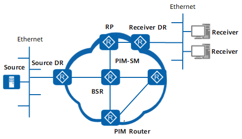
This section provides basic PIM-SM concepts, as shown in Figure 1.
PIM device
A multicast router supporting PIM is called a PIM device. A PIM-enabled interface on a PIM device is called a PIM interface.
PIM domain
A network formed by PIM devices is called a PIM network.
A BootStrap router (BSR) boundary can be configured on an interface of a multicast device to limit the transmission of BSR messages, dividing a PIM network into PIM domains. This configuration isolates multicast services and facilitates network management.
Designated router (DR)
There are two types of DRs on a PIM network:Multicast source's DR: A PIM device that is directly connected to the multicast source in a PIM-SM domain and is responsible for sending Register messages to the RP.
Receiver's DR: A PIM device that is directly connected to group members (receiver hosts) and is responsible for forwarding multicast data to the group members.
Rendezvous Point (RP)
An RPT is an MDT with an RP as the root and group members as the leaves on a PIM-SM network. The MDT is a multicast data forwarding path from a data source to multiple receivers.
An RP is the core of a PIM-SM network. Group members send Join messages to the RP to construct an RPT rooted at the RP. A multicast source registers with the RP to transmit multicast data packets to group members. The devices on the network must know the RP address. The following table lists RP classification.
Table 1 RP classification RP Type
Implementation
Deployment Scenario
Precautions
Static RP
If a static RP is used, the same RP address must be configured for all PIM devices on the network.
A static RP is recommended on small and mid-sized networks because static RPs are stable and have low requirements for device performance.
NOTE:If there is only one multicast source on the network, the device directly connected to this source should be configured as a static RP. This means that the source's DR also functions as the RP, and as a result, the source's DR does not need to register with the RP.
When a static RP is used, information about the RP and multicast groups that the RP serves must be consistent on all routers including the RP.
Dynamic RP
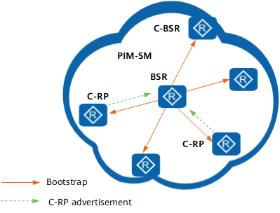
PIM devices dynamically obtain the RP address. Several PIM devices in the PIM domain are configured as Candidate-RPs (C-RPs) and Candidate BSRs (C-BSRs). A BSR is elected from the C-BSRs. The BSR collects information about the C-RPs and summarizes it into an RP-set. The RP-set is then encapsulated in BootStrap messages and advertised to all the routers in the PIM domain. Based on the RP-set, the routers in the PIM domain use the same rules to elect an RP from the C-RPs. Because all PIM devices use the same RP-set and election rules, the PIM devices have the same RP information. If the existing RP fails, a new RP is elected from the C-RPs.
A dynamic RP can be used on a large-scale network to improve network reliability and maintainability.If multiple multicast sources are densely distributed on the network, configuring core devices close to the multicast sources as C-RPs is recommended.
If multiple users are densely distributed on the network, configuring core devices close to the users as C-RPs is recommended.
If a dynamic RP is used, C-BSRs must be configured to elect a BSR. Routers on a multicast network can dynamically obtain multicast group-RP mappings from the BSR.
BSR
A BSR on a PIM-SM network collects RP information, summarizes that information into an RP-set (group-RP mapping database), and advertises the RP-set to the entire PIM-SM network.
A network can have only one BSR but can have multiple C-BSRs. If the existing BSR fails, a new BSR is elected from the C-BSRs.
RPT
An RPT is an MDT with an RP as the root and group members as the leaves.
SPT
A shortest path tree (SPT) is a multicast distribution tree (MDT) with the multicast source as the root and group members as leaves. SPTs are used in PIM-DM, PIM-SM, and PIM-SSM.
Implementation
-
Each PIM device in a PIM-SM domain periodically sends Hello messages to all other PIM devices in the domain to discover PIM neighbors and maintain PIM neighbor relationships.

By default, a PIM device permits other PIM control messages or multicast messages from a neighbor, irrespective of whether the PIM device has received Hello messages from the neighbor. However, if a PIM device has the neighbor check function, the PIM device permits other PIM control messages or multicast messages from a neighbor only after the PIM device has received Hello messages from the neighbor.
-
PIM devices exchange Hello messages to elect a DR on a shared network segment. The receiver's DR is the only multicast data forwarder on a shared network segment. The source's DR is responsible for forwarding multicast data received from the multicast source along an MDT.
-
An RP is the forwarding core in a PIM-SM domain. A dynamic or static RP forwards multicast data on the entire network.
-
PIM-SM assumes that a host requesting multicast data first sends a Join message. An RPT must be established and maintained to implement multicast data forwarding. Multicast data is sent by the RP to receivers along the RPT.
-
A multicast group in a PIM-SM domain is associated with only one RP and one RPT. All multicast data packets are forwarded by the RP. The path along which the RP forwards multicast data may not be the shortest path from the multicast source to receivers. The load of the RP increases when the multicast traffic volume increases. If the multicast data forwarding rate exceeds a configured threshold, an RPT-to-SPT switchover can be implemented to reduce the burden on the RP.
-
If there are multiple PIM devices on a network segment, the same multicast packets are sent repeatedly across the network segment. The Assert mechanism can be used to select a unique multicast data forwarder on the network segment to prevent redundant multicast data from being forwarded.
-
If the role of an interface on a PIM device is changed from DR to non-DR, the PIM device immediately stops using this interface to forward data. If multicast data sent from a new DR does not arrive, multicast data traffic is temporarily interrupted. If a DR switchover delay is configured, the interface continues to forward multicast data until the delay expires. Setting a DR switchover delay prevents multicast data traffic from being interrupted.
The detailed PIM-SM implementation process is as follows:
Neighbor Discovery
The destination address is 224.0.0.13.
The source address is an interface address.
TTL is 1, indicating that packets are sent to neighbor interfaces only.
Hello messages are used to discover neighbors, adjust protocol parameters, and maintain neighbor relationships.
Discovering PIM neighbors
All PIM devices in the same network segment must receive multicast packets with the destination address of 224.0.0.13. Directly connected multicast routers receive Hello messages that contain neighbor information.
Adjusting protocol parameters
Hello messages are used to establish and maintain neighbor relationships. A Hello message carries the following protocol parameters:
DR_Priority: priority used by the router interface to elect the DR. The interface with the highest the priority is most likely to become the DR.
Holdtime: timeout period during which the neighbor is in the reachable state.
LAN_Delay: delay for transmitting Prune message on the shared network segment.
Neighbor-Tracking: neighbor tracking function.
Override-Interval: interval carried by a Hello messages for overriding a Prune message.
Maintaining neighbor relationship
PIM devices periodically exchange Hello messages. If a PIM device does not receive a new Hello messages from its PIM neighbor within the Holdtime, the router considers the neighbor unreachable and deletes the neighbor from its neighbor list.
Changes in PIM neighbor relationships lead to the changes in the multicast topology of the network. If an upstream or a downstream neighbor in the MDT is unreachable, multicast routes reconverge and the MDT is transferred.
DR Election
As shown in Figure 2, the network segment where multicast source S or group members reside is usually connected to multiple PIM devices. The PIM devices exchange Hello messages carrying the DR priority and the interface address of the network segment and use these messages to set up PIM neighbor relationships. A PIM device compares its own information with that carried in messages sent from neighbors in a process called DR election. The election rules are as follows:
The PIM device with the highest DR priority wins (in the case that routers on the network segment support the DR priority).
If PIM devices have the same DR priority or PIM devices that do not support Hello messages carrying DR priorities exist on the network segment, the PIM device with the highest IP address wins.
RP Discovery
Static RP
If a static RP is used, the same RP address is configured on all routers and no election is required.
Dynamic RP
If a dynamic RP is used, the RP must be elected from PIM devices.
On the network shown in Figure 3, the dynamic RP election rules are as follows:C-BSRs must be configured to elect a BSR.
At first, each C-BSR considers itself a BSR and sends a Bootstrap message to the entire network. The Bootstrap message carries the address and priority of the C-BSR. Each router receives the Bootstrap message and compares the information contained in these messages. The election uses these rules to determine which C-BSR serves as BSR are as follows:The C-BSR with the highest priority wins (the greater the priority value, the higher the priority).
If the C-BSRs have the same priority, the C-BSR with the highest IP address wins.
Because all routers follow the same rules, they have the same BSR information and know the BSR address.
The C-RPs send C-RP Advertisement messages to the BSR. Each Advertisement message carries the address of the sending C-RP, the range of multicast groups that the C-RP serves, and the priority of the C-RP.
The BSR collects information for an RP-set, encapsulates it in a Bootstrap message, and advertises it to each PIM-SM device on the entire network.
- Each router uses the RP-set to perform the same calculations and comparisons to select the RP of this group from the multiple C-RPs to which a specific group corresponds. The election rules are as follows:
A C-RP wins if it serves the group address that users join has the longest mask.
If group addresses that users join and are served by C-RPs have the same mask length, the priorities of the C-RPs are compared. The C-RP with the highest priority wins (the greater the priority value, the lower the priority).
If the C-RPs have same priority, hash functions are run. The C-RP with the greatest calculated value wins.
If none of the above criteria can determine a winner, the C-RP with the highest address wins.
Because all routers use the same RP-set and the same election rules, the relationship between the multicast group and the RP is the same for all routers. Routers save this relationship to guide subsequent multicast operations.
If a router needs to be interwork with an auto-RP-capable device, enable auto-RP listening. After auto-RP listening is enabled, the router can receive auto-RP announcement and discovery messages, parses the source addresses of the messages, and performs Reverse Path Forwarding (RPF) checks based on the source addresses.
- If the RPF checks fail, the router discards the messages.
- If the RPF checks are successful, the router forwards the messages carrying the address range of the multicast group served by the RP to other PIM neighbors to guide subsequent multicast operations.
Auto-RP listening is supported only in IPv4 scenarios.
Anycast RP
In a traditional PIM-SM domain, each multicast group is mapped to a single RP. If the network becomes overloaded or the traffic is too concentrated, a variety of network problems can result. For example, there is too much pressure on the RP, the router converges slowly if the RP fails, or the multicast forwarding path is not optimal.
Anycast RP addresses the previous issue. The FW can use MSDP to set RPs with the same address in a PIM-SM domain, and the RPs establish MSDP peer relationships to share multicast data source information.
RPT Setup
A PIM-SM RPT is an MDT that uses the RP as a root and group member routers as leaves.
The RP is an important PIM device on the network and is responsible for handling Register message from source's DRs and Join messages from members. All PIM devices on the network are aware of the location of the RP that acts as a convergence center of supply and demand information.
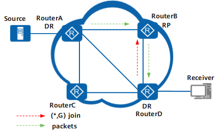
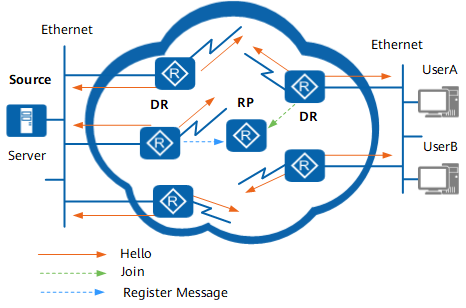
Setting up an RPT creates a forwarding path for multicast data. Figure 4 shows the process of RPT setup and data forwarding.
When a multicast source becomes active on the network (that is, when the source sends the first multicast packet to a multicast group G), the source's DR encapsulates the multicast packet in a Register message and unicasts the Register message to the RP. An (S, G) entry is created on the RP and source information is registered.
When a new group member appears on the network (that is, when a user host joins a multicast group G through IGMP), the receiver's DR on the group member side sends a Join message to the RP. A (*, G) entry is created hop by hop and an RPT with the RP as the root is generated.
When a group member and a multicast source that sends multicast data to the group appear on the network, multicast data is encapsulated in a Join message and then unicasted to the RP. The RP then forwards the multicast data along the RPT to group members.
RPT implements on-demand multicast data forwarding and reduces the usage of network bandwidth by data that is not demanded.
To reduce the forwarding workload of the RPT and improve forwarding efficiency of multicast data, PIM-SM allows SPT switchovers. A direct forwarding link is set up from the multicast source to the receiver so that the multicast source can forward multicast data to the receiver along the SPT.
SPT Switchover
A PIM-SM SPT is an MDT with the multicast source as the root and the group members as leaves.
A multicast group in a PIM-SM network is associated with only one RP and only one RPT is set up for a multicast group. Before an SPT switchover is performed, all multicast packets destined for a multicast group must be encapsulated in Register message and then sent to the RP. The RP decapsulates the packets and forwards them along the RPT to the multicast group.
All multicast packets forwarded along the RPT are transferred by the RP. The RP can become over burdened when multicast traffic is heavy. To resolve this problem, PIM-SM allows the RP or the receiver's DR to trigger an SPT switchover.
There are two ways to trigger an SPT switchover:
SPT switchover triggered by the RP
Register message sent from the source's DR are decapsulated by the RP, which then forwards multicast data along the RPT to group members. At the same time, the RP sends SPT Join message to the source's DR to set up an SPT from the RP to the source.
After the SPT is set up and starts carrying multicast data packets, the RP stops processing Register message. This frees the source's DR and RP from encapsulating and decapsulating packets. Multicast data is sent from the router directly connected to the multicast source to the RP along the SPT and then forwarded to group members through the RPT.
- SPT switchover triggered by the receiver's DR
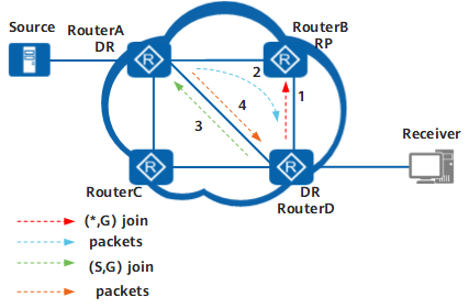
As shown in Figure 5, multicast data is transmitted along the RPT. The receiver's DR (Router D) sends (*, G) Join message to the RP. Multicast data is sent to receivers along the path source's DR (Router A)->RP (Router B)-> receiver's DR (Router D).
The receiver's DR periodically checks the forwarding rate of multicast packets. If the receiver's DR finds that the forwarding rate is greater than a configured threshold, the DR triggers SPT switchover.
The receiver's DR sends (S, G) Join messages to the source's DR. After receiving multicast data along the SPT, the receiver's DR discards multicast data received along the RPT and sends a Prune message to the RP to delete the receiver from the RPT. The switchover from the RPT to the SPT is complete.
Multicast data is forwarded along the SPT. Specifically, multicast data is transmitted to receivers along the path multicast source's DR (Router A) -> receiver's DR (Router D).
An SPT is set up from the source to group members, and therefore subsequent packets may bypass the RP. The RPT may not be an SPT. After SPT switchover is performed, delays in transmitting multicast data on the network are reduced.
It is possible for one source on the network to send packets to multiple groups simultaneously. If an SPT switchover policy is specified for a specified group range, the following points apply:
- Before SPT switchover, these packets reach the receiver's DR along the RPT.
- After SPT switchover, only the packets sent to the groups within the range specified in the SPT switchover policy are forwarded along the SPT. Packets sent to other groups are still forwarded along the RPT.
By default, the RP performs SPT switchover immediately after receiving the first Register message, and the receiver's DR performs SPT switchover immediately after receiving the first multicast packet.
Assert
If the following conditions are met, other multicast forwarders exist on the network segment:
A multicast packet fails the RPF check.
The interface that receives the multicast packet is a downstream interface in the (S,G) entry on the local router.
If either of these conditions exists, the router applies the Assert mechanism.
The router sends an Assert message through the downstream interface. The downstream interface also receives an Assert message from a different multicast forwarder on the network segment. The destination address of the multicast packet in which the Assert message is encapsulated is 224.0.0.13; the source address of the packet is the downstream interface address; the TTL value of the packet is 1. The Assert message carries the route cost from the PIM device to source or RP, priority of the used unicast routing protocol, and the group address.
The router with the highest unicast routing protocol priority wins.
If the routers have the same unicast routing protocol priority, the router with the smaller route cost to S wins.
If the routers have the same priority and route cost, the router with the highest IP address for the downstream interface wins.
The router performs the following operations based on the Assert election result:
If the router wins, the downstream interface of the router is responsible for forwarding multicast packets on the network segment. The downstream interface is called an Assert winner.
If the router loses, the downstream interface is prohibited from forwarding multicast packets and deleted from the downstream interface list of the (S,G) entry. The downstream interface is called an Assert loser.
After the Assert election is complete, only one upstream router that has a downstream interface exists on the network segment and the downstream interface transmits only one copy of multicast traffic. The Assert winner then periodically sends Assert message to maintain its status as the Assert winner. If the Assert loser does not receive any Assert message from the Assert winner after the timer of the Assert loser expires, it re-adds downstream interfaces for multicast data forwarding.
DR Switchover Delay
If an existing DR becomes faulty, the PIM neighbor relationship times out, and a new DR election is triggered.
By default, when an interface changes from a DR to a non-DR, the router immediately stops using the interface to forward data. If multicast data sent from a new DR has not yet arrived at the interface, multicast data streams are temporarily interrupted.
When a PIM-SM interface that has a PIM DR switchover delay set receives Hello messages from a new neighbor and changes from a DR to a non-DR, it continues to function as a DR and to forward multicast packets until the delay times out.
If the router configured with the DR switchover delay receives packets from a new DR before the delay expires, the router immediately stops forwarding packets. When a new IGMP Report message is received on the shared network segment, the new DR (instead of the old DR configured with the DR switchover delay) sends a PIM Join message to the upstream device.
If the new DR receives multicast data from the original DR before the DR switchover delay expires, an Assert election is triggered.
PIM-SM Administrative Domain
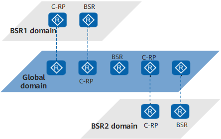
A PIM-SM network is divided into multiple BSR administrative domains and a global domain to facilitate management needs. Dividing the network into domains can reduce the workloads of a single BSR and can use private group address to provide special services for users in a specific domain.
Each BSR administrative domain has only one BSR that serves a multicast group for a specific address range. The global domain has a BSR that serves the other multicast groups.
The relationship between the BSR administrative domain and the global domain is described as follows in terms of the domain space, group address range, and multicast function.
Domain space
As shown in Figure 6, different BSR administrative domains contain different routers. A router cannot belong to multiple BSR administrative domains. Each BSR administrative domain is independent and geographically isolated from domain. A BSR administrative domain manages a multicast group for a specific address range. The multicast packet within this range can be transmitted only in this BSR administrative domain and cannot exit the border of the domain.
The global domain contains all the routers on the PIM-SM network. The multicast packet that does not belong to a particular BSR administrative domain can be transmitted over the entire PIM network.
Group address range
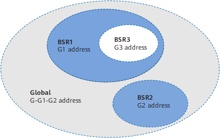
Each BSR administrative domain provides services for the multicast group within the specific address range. The multicast groups that different BSR administrative domains serve can overlap. The address of a multicast group that the BSR administrative domain serves is valid only in its BSR administrative domain. To be specific, the multicast address is used as the private group address. As shown in Figure 7, the group address range of BSR1 and that of the BSR3 overlap.
The multicast group that does not belong to any BSR administrative domain belongs to the global domain. That is, the group address range of the global domain is G-G1-G2.
Multicast function
As shown in Figure 6, the global domain and each BSR administrative domain have their respective C-RP and BSR devices. Devices only function in the domain to which they are assigned. Each BSR administrative domain has a BSR mechanism and RP elections that are independent of other domains.
Each BSR administrative domain has a border. Multicast information for this domain, such as the C-RP Advertisement messages and BSR Bootstrap message, can be transmitted only within the domain. Multicast information for the global domain can be transmitted throughout the entire global domain and can traverse any BSR administrative domain.