Example for Configuring PIM-SM Inter-Domain Multicast
You can set up MSDP peer relationships between Rendezvous Points (RPs) in different PIM-SM domains in the same AS or between the RPs in different ASs that have set up External BGP (EBGP) peer relationships so that hosts can receive multicast data from the source in another PIM-SM domain in the AS or from the source in another AS.
Networking Requirements
As shown in Figure 1, there are two ASs in the network. Each AS contains one or more PIM-SM domains, and each PIM-SM domain may contain one multicast source and receiver, or none at all. The receivers in PIM-SM2 domain are required to receive multicast data sent by S3 in PIM-SM3 domain and multicast data sent by S1 in PIM-SM1 domain.
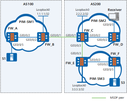
Device |
Interface |
IP address |
|---|---|---|
FW_A |
GE0/0/5 |
10.110.1.1/24 |
GE0/0/2 |
192.168.1.1/24 |
|
FW_B |
GE0/0/1 |
192.168.2.1/24 |
GE0/0/2 |
192.168.1.2/24 |
|
FW_C |
GE0/0/1 |
192.168.2.2/24 |
GE0/0/2 |
192.168.3.1/24 |
|
GE0/0/3 |
192.168.4.1/24 |
|
FW_D |
GE0/0/5 |
10.110.2.1/24 |
GE0/0/2 |
192.168.3.2/24 |
|
FW_E |
GE0/0/2 |
192.168.5.1/24 |
GE0/0/3 |
192.168.4.2/24 |
|
FW_F |
GE0/0/5 |
10.110.3.1/24 |
GE0/0/2 |
192.168.5.2/24 |
Configuration Roadmap
Solution: configure MSDP peer relationships between RPs of each PIM-SM domain. The configuration roadmap is as follows:
Configure IP addresses of interfaces on each FW, and configure OSPF in the ASs to ensure that unicast routes are reachable in the ASs.
Configure External BGP (EBGP) peers between ASs and configure BGP and OSPF to import routes to each other to ensure that unicast routes are reachable.
Enable multicast and PIM-SM on each interface, configure the boundary of a domain, and enable IGMP on the interface connected to hosts.
Configure a Candidate-BSR (C-BSR) and a Candidate-RP (C-RP). Configure the RPs of PIM-SM1 and PIM-SM2 on autonomous system boundary routers (ASBRs).
Establish the MSDP peer relationship between RPs of each domain. MSDP peers and EBGP peers between ASs use the same interface address. According to Reverse Path Forwarding (RPF) rules, FWs receive Source Active (SA) messages forwarded by the next hop of the route to the source RP.
Procedure
- Configure an IP address and a unicast routing protocol on each FW.
Configure an IP address and mask on each interface as shown in Figure 1. Configure OSPF in the AS. Ensure that the communication between FWs is normal at the network layer. Ensure dynamic routing updates between FWs with the help of the unicast routing protocol. The procedures are not mentioned here.
- Configure BGP between ASs and configure BGP and OSPF to import routes each other.
# Configure EBGP on FW_B and import OSPF routes.
[FW_B] bgp 100[FW_B-bgp] router-id 1.1.1.1[FW_B-bgp] peer 192.168.2.2 as-number 200[FW_B-bgp] import-route ospf 1[FW_B-bgp] quit# Configure EBGP on FW_C, and then import OSPF routes.
[FW_C] bgp 200[FW_C-bgp] router-id 2.2.2.2[FW_C-bgp] peer 192.168.2.1 as-number 100[FW_C-bgp] import-route ospf 1[FW_C-bgp] quit# Import BGP routes to OSPF on FW_B. The configuration of FW_C is similar to that of FW_B, and is not mentioned here.
[FW_B] ospf 1[FW_B-ospf-1] import-route bgp[FW_B-ospf-1] quit - Enable multicast on each FWand enable PIM-SM on each interface, configure the boundary of a domain and enable IGMP on the interface connected to hosts.
# Enable multicast on FW_B, and enable PIM-SM on each interface. The configurations of other FWs are similar to that of FW_B, and are not mentioned here.
[FW_B] multicast routing-enable[FW_B] interface GigabitEthernet 0/0/2
[FW_B-GigabitEthernet0/0/2] pim sm
[FW_B-GigabitEthernet0/0/2] quit
[FW_B] interface GigabitEthernet 0/0/1
[FW_B-GigabitEthernet0/0/1] pim sm
# Configure the BSR boundary on GE0/0/1 of FW_B.
[FW_B-GigabitEthernet0/0/1] pim bsr-boundary
[FW_B-GigabitEthernet0/0/1] quit
Configure the domain boundary on GE0/0/1 and GE0/0/3 of FW_C and the BSR service boundary on GE0/0/3 of FW_E. The configurations of FW_C and FW_E are similar to that of FW_B, and are not mentioned here.
# Enable IGMP on interface through which FW_D is connected to the leaf network.
[FW_D] interface GigabitEthernet 0/0/5
[FW_D-GigabitEthernet0/0/5] igmp enable
- Configure a C-BSR and a C-RP.
# Configure Loopback 0 interfaces and C-BSRs and C-RPs on FW_B. The configurations of FW_C and FW_E are similar to those of FW_B, and are not mentioned here.
[FW_B] interface loopback 0[FW_B-LoopBack0] ip address 1.1.1.1 255.255.255.255[FW_B-LoopBack0] pim sm[FW_B-LoopBack0] quit[FW_B] pim[FW_B-pim] c-bsr loopback 0[FW_B-pim] c-rp loopback 0[FW_B-pim] quit - Configure MSDP peers.
# Configure MSDP peers on FW_B.
[FW_B] msdp[FW_B-msdp] peer 192.168.2.2 connect-interface GigabitEthernet 0/0/1
[FW_B-msdp] quit# Configure MSDP peers on FW_C.
[FW_C] msdp[FW_C-msdp] peer 192.168.2.1 connect-interface GigabitEthernet 0/0/1
[FW_C-msdp] peer 192.168.4.2 connect-interface GigabitEthernet 0/0/3
[FW_C-msdp] quit# Configure MSDP peers on FW_E.
[FW_E] msdp[FW_E-msdp] peer 192.168.4.1 connect-interface GigabitEthernet 0/0/3
[FW_E-msdp] quit - Verify the configuration.
# Run the display bgp peer command. You can view BGP peer relationships between FWs. For example, the BGP peer relationship between FW_B and FW_C is as follows:
<FW_B> display bgp peerBGP local router ID : 1.1.1.1
Local AS number : 100
Total number of peers : 1 Peers in established state : 1
Peer V AS MsgRcvd MsgSent OutQ Up/Down State PrefRcv
192.168.2.2 4 200 24 21 0 00:13:09 Established 6
<FW_C> display bgp peerBGP local router ID : 2.2.2.2
Local AS number : 200
Total number of peers : 1 Peers in established state : 1
Peer V AS MsgRcvd MsgSent OutQ Up/Down State PrefRcv
192.168.2.1 4 100 18 16 0 00:12:04 Established 1
# Run the display bgp routing-table command. You can view the BGP routing table on a FW. For example, the BGP routing table on FW_C is as follows:
<FW_C> display bgp routing-tableTotal Number of Routes: 5
BGP Local router ID is 2.2.2.2
Status codes: * - valid, > - best, d - damped,
h - history, i - internal, s - suppressed, S - Stale
Origin : i - IGP, e - EGP, ? - incomplete
       Network            NextHop         MED        LocPrf    PrefVal Path/Ogn
 *>    1.1.1.1/32         192.168.2.1     0                    0       100?
 *>i   2.2.2.2/32         0.0.0.0         0                    0       ?
 *>    192.168.2.0        0.0.0.0         0                    0       ?
 *>    192.168.2.1/32     0.0.0.0         0                    0       ?
 *>    192.168.2.2/32     0.0.0.0         0                    0       ?
# Run the display msdp brief command. You can view MSDP peer relationships between FWs. The brief information about MSDP peer relationships between FW_B, FW_C, and FW_E is as follows:
<FW_B> display msdp briefMSDP Peer Brief Information of VPN-Instance: public net
Configured Up Listen Connect Shutdown Down
1 1 0 0 0 0
Peer's Address State Up/Down time AS SA Count Reset Count
192.168.2.2 UP 00:12:27 200 13 0
<FW_C> display msdp briefMSDP Peer Brief Information of VPN-Instance: public net
Configured Up Listen Connect Shutdown Down
2 2 0 0 0 0
Peer's Address State Up/Down time AS SA Count Reset Count
192.168.2.1 UP 01:07:08 100 8 0
192.168.4.2 UP 00:06:39 200 13 0
<FW_E> display msdp briefMSDP Peer Brief Information of VPN-Instance: public net
Configured Up Listen Connect Shutdown Down
1 1 0 0 0 0
Peer's Address State Up/Down time AS SA Count Reset Count
192.168.4.1 UP 00:15:32 200 8 0
# Run the display msdp peer-status command. You can view the detailed information about the MSDP peers. The detailed information about MSDP peers on FW_B is as follows:
<FW_B> display msdp peer-statusMSDP Peer Information of VPN-Instance: public net
MSDP Peer 192.168.2.2, AS 200
Description:
Information about connection status:
State: Up
Up/down time: 00:15:47
Resets: 0
Connection interface: GigabitEthernet 0/0/1 (192.168.2.1)Number of sent/received messages: 16/16
Number of discarded output messages: 0
Elapsed time since last connection or counters clear: 00:17:51
Information about (Source, Group)-based SA filtering policy:
Import policy: none
Export policy: none
Information about SA-Requests:
Policy to accept SA-Request messages: none
Sending SA-Requests status: disable
Minimum TTL to forward SA with encapsulated data: 0
SAs learned from this peer: 0, SA-cache maximum for the peer: none
Input queue size: 0, Output queue size: 0
Counters for MSDP message:
Count of RPF check failure: 0
Incoming/outgoing SA messages: 0/0
Incoming/outgoing SA requests: 0/0
Incoming/outgoing SA responses: 0/0
Incoming/outgoing data packets: 0/0
    Peer authentication: not configured
    Peer authentication type: none
# Run the display pim routing-table command. You can view the PIM routing table on a FW. When S1 (10.110.1.2/24) in PIM-SM1 domain and S3 (10.110.3.2/24) in PIM-SM3 domain send multicast data to G (225.1.1.1/24), Receiver (10.110.2.2/24) in PIM-SM2 domain can receive the multicast data. The information about the PIM routing tables on FW_B and FW_C is as follows:
<FW_B> display pim routing-tableVPN-Instance: public net
Total 0 (*, G) entry; 1 (S, G) entry
(10.110.1.2, 225.1.1.1)
RP: 1.1.1.1(local)
Protocol: pim-sm, Flag: SPT EXT ACT
UpTime: 00:00:42
Upstream interface: GigabitEthernet 0/0/2Upstream neighbor: 192.168.1.1
RPF neighbor: 192.168.1.1
Downstream interface(s) information:
Total number of downstreams: 1
1: GigabitEthernet 0/0/1Protocol: pim-sm, UpTime: 00:00:42, Expires:-
<FW_C> display pim routing-tableVPN-Instance: public net
Total 1 (*, G) entry; 2 (S, G) entries
(*, 225.1.1.1)
RP: 2.2.2.2(local)
Protocol: pim-sm, Flag: WC RPT
UpTime: 00:13:46
Upstream interface: NULL,
Upstream neighbor: NULL
RPF prime neighbor: NULL
Downstream interface(s) information:
Total number of downstreams: 1
1: GigabitEthernet 0/0/2,Protocol: pim-sm, UpTime: 00:13:46, Expires:-
(10.110.1.2, 225.1.1.1)
RP: 2.2.2.2
Protocol: pim-sm, Flag: SPT MSDP ACT
UpTime: 00:00:42
Upstream interface: GigabitEthernet 0/0/1Upstream neighbor: 192.168.2.1
RPF neighbor: 192.168.2.1
Downstream interface(s) information:
Total number of downstreams: 1
1: GigabitEthernet 0/0/2Protocol: pim-sm, UpTime: 00:00:42, Expires:-
(10.110.3.2, 225.1.1.1)
RP: 2.2.2.2
Protocol: pim-sm, Flag: SPT MSDP ACT
UpTime: 00:00:42
Upstream interface: GigabitEthernet 0/0/3Upstream neighbor: 192.168.4.2
RPF neighbor: 192.168.4.2
Downstream interface(s) information:
Total number of downstreams: 1
1: GigabitEthernet 0/0/2Protocol: pim-sm, UpTime: 00:00:42, Expires:-
Configuration Scripts
Configuration script of FW_B
#
sysname FW_B#
multicast routing-enable
#
interface GigabitEthernet 0/0/2ip address 192.168.1.2 255.255.255.0
pim sm
#
interface GigabitEthernet 0/0/1ip address 192.168.2.1 255.255.255.0
pim sm
pim bsr-boundary
#
interface LoopBack0
ip address 1.1.1.1 255.255.255.255
pim sm
#
bgp 100
router-id 1.1.1.1
peer 192.168.2.2 as-number 200
import-route ospf 1
#
ospf 1
import-route bgp
area 0.0.0.0
network 192.168.1.0 0.0.0.255
network 1.1.1.1 0.0.0.0
#
pim
c-bsr LoopBack0
c-rp LoopBack0
#
msdp
peer 192.168.2.2 connect-interface GigabitEthernet 0/0/1#
return
Configuration script of FW_C
#
sysname FW_C#
multicast routing-enable
#
interface GigabitEthernet 0/0/1ip address 192.168.2.2 255.255.255.0
pim sm
pim bsr-boundary
#
interface GigabitEthernet 0/0/2ip address 192.168.3.1 255.255.255.0
pim sm
#
interface GigabitEthernet 0/0/3ip address 192.168.4.1 255.255.255.0
pim sm
pim bsr-boundary
#
interface LoopBack0
ip address 2.2.2.2 255.255.255.255
pim sm
#
bgp 200
router-id 2.2.2.2
peer 192.168.2.1 as-number 100
import-route ospf 1
#
ospf 1
import-route bgp
area 0.0.0.0
network 192.168.3.0 0.0.0.255
network 192.168.4.0 0.0.0.255
network 2.2.2.2 0.0.0.0
#
pim
c-bsr LoopBack0
c-rp LoopBack0
#
msdp
peer 192.168.2.1 connect-interface GigabitEthernet 0/0/1peer 192.168.4.2 connect-interface GigabitEthernet 0/0/3#
return
Configuration script of FW_E
#
sysname FW_E#
multicast routing-enable
#
interface GigabitEthernet 0/0/2ip address 192.168.5.1 255.255.255.0
pim sm
#
interface GigabitEthernet 0/0/3ip address 192.168.4.2 255.255.255.0
pim sm
pim bsr-boundary
#
interface LoopBack0
ip address 3.3.3.3 255.255.255.255
pim sm
#
ospf 1
area 0.0.0.0
network 192.168.4.0 0.0.0.255
network 192.168.5.0 0.0.0.255
network 3.3.3.3 0.0.0.0
#
pim
c-bsr LoopBack0
c-rp LoopBack0
#
msdp
peer 192.168.4.1 connect-interface GigabitEthernet 0/0/3#
return