Example for Configuring Anycast RP
If there are multiple multicast sources and receivers in a PIM-SM domain, you can configure MSDP peer relationships between Candidate-RPs (C-RPs) and configure anycast Rendezvous Point (RP) to implement load sharing.
Networking Requirements
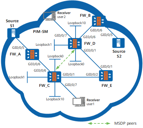
As shown in Figure 1, the PIM-SM domain has multiple multicast sources and receivers. It is required to set up MSDP peers in the PIM-SM domain to implement RP load balancing.
Device |
Interface |
IP address |
|---|---|---|
FW_A |
GE0/0/5 |
10.110.5.1/24 |
GE0/0/6 |
10.110.1.2/24 | |
| FW_B | GE0/0/5 |
10.110.6.1/24 |
GE0/0/6 |
10.110.2.2/24 | |
| FW_C | GE0/0/1 |
192.168.1.1/24 |
GE0/0/6 |
10.110.1.1/24 | |
GE0/0/7 |
10.110.4.1/24 | |
Loopback0 |
1.1.1.1/32 | |
Loopback1 |
3.3.3.3/32 | |
Loopback10 |
10.1.1.1/32 | |
| FW_D | GE0/0/1 |
192.168.3.1/24 |
GE0/0/6 |
10.110.2.1/24 | |
GE0/0/7 |
10.110.3.1/24 | |
Loopback0 |
2.2.2.2/32 | |
Loopback1 |
4.4.4.4/32 | |
Loopback10 |
10.1.1.1/32 | |
| FW_E | GE0/0/1 |
192.168.3.2/24 |
GE0/0/2 |
192.168.1.2/24 |
Configuration Roadmap
Solution: Configure an anycast RP. The receiver sends a Join message to the RP closest to the topology. The source sends a Register message to the RP closest to the topology. The steps are as follows:
Configure an IP address for each interface and configure OSPF in the PIM-SM area.
Enable multicast on each FWand PIM-SM on each interface and enable IGMP on the interface connected to hosts.
Configure the same loopback interface address for FW_C and FW_D. Configure the Candidate-BSR (C-BSR) on Loopback 1 interfaces and the C-RP on Loopback 10 interfaces.
Configure MSDP peers on Loopback 0 interfaces of FW_C and FW_D. According to Reverse Path Forwarding (RPF) rules, FWs receive Source Active (SA) messages from the source RP.
Procedure
- Configure an IP address on each interface and a unicast
routing protocol.
Configure an IP address and mask to each interface according to Figure 1. Configure OSPF. Ensure the communication between FWs on the network layer. Ensure dynamic routing updates between FWs by means of the unicast routing protocol. The procedures are not mentioned here.
- Enable multicast on each FWand configure PIM-SM
on each interface.
Enable multicast on each FW, and enable PIM-SM on each interface. Enable IGMP on the interface connected to hosts. The configurations of other FWs are similar to that of FW_C, and are not mentioned here.
[FW_C] multicast routing-enable[FW_C] interface GigabitEthernet 0/0/7
[FW_C-GigabitEthernet0/0/7] igmp enable
[FW_C-GigabitEthernet0/0/7] pim sm
[FW_C-GigabitEthernet0/0/7] quit
[FW_C] interface GigabitEthernet 0/0/6
[FW_C-GigabitEthernet0/0/6] pim sm
[FW_C-GigabitEthernet0/0/6] quit
[FW_C] interface GigabitEthernet 0/0/1
[FW_C-GigabitEthernet0/0/1] pim sm
[FW_C-GigabitEthernet0/0/1] quit
- Configure Loopback 1 and Loopback 10 interfaces, and the
C-BSR and C-RP.
Configure the address of Loopback 1 interface and the address of Loopback 10 interface on FW_C and FW_D respectively. Configure the C-BSP on Loopback 1 and the C-RP on Loopback 10. The configurations of FW_D are similar to that of FW_C, and are not mentioned here.
[FW_C] interface loopback 1[FW_C-LoopBack1] ip address 3.3.3.3 255.255.255.255[FW_C-LoopBack1] pim sm[FW_C-LoopBack1] quit[FW_C] interface loopback 10[FW_C-LoopBack10] ip address 10.1.1.1 255.255.255.255[FW_C-LoopBack10] pim sm[FW_C-LoopBack10] quit[FW_C] pim[FW_C-pim] c-bsr loopback 1[FW_C-pim] c-rp loopback 10[FW_C-pim] quit - Configure Loopback 0 interfaces and MSDP peers.
# Configure MSDP peers on the Loopback 0 interfaces of FW_C.
[FW_C] interface loopback 0[FW_C-LoopBack0] ip address 1.1.1.1 255.255.255.255[FW_C-LoopBack0] pim sm[FW_C-LoopBack0] quit[FW_C] msdp[FW_C-msdp] originating-rp loopback0[FW_C-msdp] peer 2.2.2.2 connect-interface loopback0[FW_C-msdp] quit# Configure MSDP peers on the Loopback 0 interfaces of FW_D.
[FW_D] interface loopback 0[FW_D-LoopBack0] ip address 2.2.2.2 255.255.255.255[FW_D-LoopBack0] pim sm[FW_D-LoopBack0] quit[FW_D] msdp[FW_D-msdp] originating-rp loopback0[FW_D-msdp] peer 1.1.1.1 connect-interface loopback0[FW_D-msdp] quit - Verify the configuration.
# Run the display msdp brief command. You can view the MSDP peer relationships between FWs. The MSDP peer relationship between FW_C and FW_D is as follows:
[FW_C] display msdp briefMSDP Peer Brief Information of VPN-Instance: public net
Configured Up Listen Connect Shutdown Down
1 1 0 0 0 0
Peer's Address State Up/Down time AS SA Count Reset Count
2.2.2.2 Up 00:10:17 ? 0 0
[FW_D] display msdp briefMSDP Peer Brief Information of VPN-Instance: public net
Configured Up Listen Connect Shutdown Down
1 1 0 0 0 0
Peer's Address State Up/Down time AS SA Count Reset Count
1.1.1.1 Up 00:10:18 ? 0 0
# Run the display pim routing-table command. You can view PIM routes on a FW. In the PIM-SM domain, S1 (10.110.5.100/24) sends multicast information to G (225.1.1.1). User 1 that joins G receives the multicast data sent to G. Comparing with the display of PIM routes on FW_C and FW_D, you can find that the valid RP is FW_C. That is, S1 registers with FW_C, and User 1 sends Join messages to FW_C.
<FW_C> display pim routing-tableVPN-Instance: public net
Total 1 (*, G) entry; 1 (S, G) entry
(*, 225.1.1.1)
RP: 10.1.1.1 (local)
Protocol: pim-sm, Flag: WC
UpTime: 00:28:49
Upstream interface: Register
Upstream neighbor: NULL
RPF prime neighbor: NULL
Downstream interface(s) information:
Total number of downstreams: 1
1: GigabitEthernet0/0/7Protocol: static, UpTime: 00:28:49, Expires: -
(10.110.5.1, 225.1.1.1)
RP: 10.1.1.1 (local)
Protocol: pim-sm, Flag: SPT 2MSDP ACT
UpTime: 00:02:26
Upstream interface: GigabitEthernet0/0/6Upstream neighbor: 10.110.1.2
RPF prime neighbor: 10.110.1.2
Downstream interface(s) information:
Total number of downstreams: 1
1: GigabitEthernet0/0/7Protocol: pim-sm, UpTime: 00:02:26, Expires: -
<FW_D> display pim routing-tableThere is no display.
# User 1 leaves G, and S1 stops sending multicast data to G. You can run the reset multicast routing-table all and reset multicast forwarding-table all commands to clear the multicast routing entries and multicast forwarding entries on FW_C.
# User 2 joins G, and S2 (10.110.6.100/24) sends multicast data to G. Comparing with the display of PIM routes on FW_C and FW_D, you can find that the valid RP is FW_D. That is, S2 registers with FW_D, and User 2 sends Join messages to FW_D.
<FW_C> reset multicast routing-table all<FW_C> reset multicast forwarding-table allThere is no display.
<FW_D> display pim routing-tableVPN-Instance: public net
Total 1 (*, G) entry; 1 (S, G) entry
(*, 225.1.1.1)
RP: 10.1.1.1 (local)
Protocol: pim-sm, Flag: WC RPT
UpTime: 00:07:23
Upstream interface: NULL,
Upstream neighbor: NULL
RPF prime neighbor: NULL
Downstream interface(s) information:
Total number of downstreams: 1
1: GigabitEthernet0/0/7,Protocol: pim-sm, UpTime: 00:07:23, Expires:-
(10.110.6.100, 225.1.1.1)
RP: 10.1.1.1 (local)
Protocol: pim-sm, Flag: SPT 2MSDP ACT
UpTime: 00:10:20
Upstream interface: GigabitEthernet0/0/6Upstream neighbor: 10.110.2.2
RPF prime neighbor: 10.110.2.2
Downstream interface(s) information:
Total number of downstreams: 1
1: GigabitEthernet0/0/7Protocol: pim-sm, UpTime: 00:10:22, Expires: -
Configuration Scripts
Configuration script of FW_C:
#
sysname FW_C
#
multicast routing-enable
#
interface GigabitEthernet0/0/7
ip address 10.110.4.1 255.255.255.0
igmp enable
pim sm
#
interface GigabitEthernet0/0/6
ip address 10.110.1.1 255.255.255.0
pim sm
#
interface GigabitEthernet0/0/1
ip address 192.168.1.1 255.255.255.0
pim sm
#
interface LoopBack0
ip address 1.1.1.1 255.255.255.255
pim sm
#
interface LoopBack1
ip address 3.3.3.3 255.255.255.255
pim sm
#
interface LoopBack10
ip address 10.1.1.1 255.255.255.255
pim sm
#
ospf 1
area 0.0.0.0
network 10.110.1.0 0.0.0.255
network 10.110.4.0 0.0.0.255
network 1.1.1.1 0.0.0.0
network 3.3.3.3 0.0.0.0
network 10.1.1.1 0.0.0.0
network 192.168.1.0 0.0.0.255
#
pim
c-bsr LoopBack1
c-rp LoopBack10
#
msdp
originating-rp LoopBack0
peer 2.2.2.2 connect-interface LoopBack0
#
return
The configuration of FW_D is similar to that of FW_C, and is not mentioned here.