Web: Example for Configuring Single-Server Smart DNS in Round Robin Mode
This section provides an example for configuring single-server smart DNS in round robin mode on the web UI.
Networking Requirements
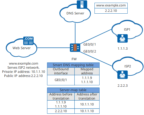
On the enterprise network shown in Figure 1, a web server with the domain name www.example.com is deployed to provide services for Internet users. The private address of the server is 10.1.1.10, and the public address is 2.2.2.10. The DNS server has the mapping between the domain name www.example.com and the public address 2.2.2.10.
The enterprise requires that when ISP1 users access www.example.com, the domain name be resolved to the public address 2.2.2.10 of the web server, the access traffic be transmitted over the ISP1 network to the FW, and the FW use the NAT Server function to map the public address to the private address 10.1.1.10 of the web server.
Configuration Roadmap
As shown in Figure 1, you can configure round robin-based smart DNS to enable the FW to allocate addresses to users based on weights. The FW changes the destination addresses of user access requests to divert traffic to web servers over various links, implementing load balancing. The configuration roadmap is as follows:
Enable smart DNS.
Configure round robin-based single-server smart DNS.
- Configure NAT Server.
Configure a NAT Server mapping for the FW to translate ISP1 public IP addresses 1.1.1.9 and 1.1.1.10 to the private IP address 10.1.1.10 of the web server, so that ISP1 users can access the web server using the public IP addresses.
Configure sticky load balancing.
Procedure
- Choose .
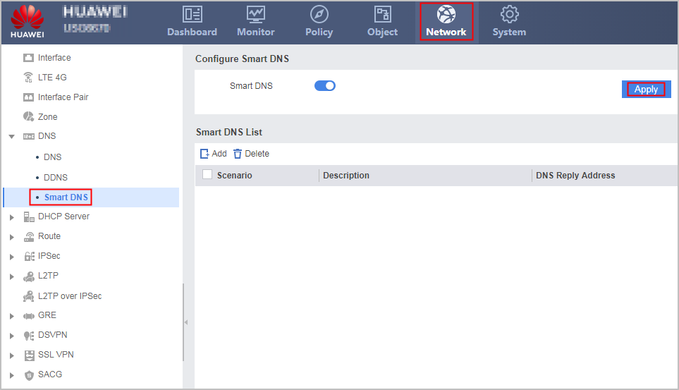
- Enable Smart DNS, and click Apply.
- In Smart DNS List, click Add.
- In the Create Smart DNS dialog box, set single-server smart DNS parameters, so that the FW replies to ISP1 users with the web server's public addresses 1.1.1.9 and 1.1.1.10.
Scenario
Single-server
DNS Reply Address
2.2.2.10
Traffic Distribution Mode
Round Robin
ISP WAN Interface
GigabitEthernet 0/0/1
ISP Server Public Address
1.1.1.9
1.1.1.10
- Click OK.
- Choose .
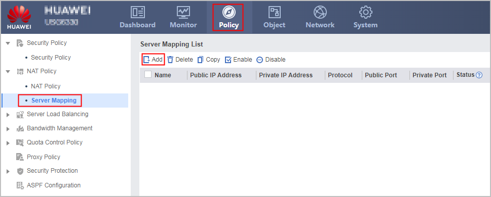
- In Server Mapping List, click Add.
- In the Add Address Mapping dialog box, set NAT Server mappings, so that the FW translates the public addresses 1.1.1.9 and 1.1.1.10 of the web server to the private address 10.1.1.10.
Name
isp1_server_nat1
isp1_server_nat2
Public IP Address
1.1.1.9
1.1.1.10
Private IP Address
10.1.1.10
10.1.1.10
- Click OK.
- Choose .
- Click
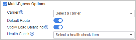
 of GigabitEthernet 0/0/1, select Multi-egress options, and set sticky load balancing parameters. In the example, basic interface settings (such as interface IP addresses and default gateway addresses) have been completed.
The sticky load balancing function can be configured only after the IP address and gateway address are set on the interface.
Configuration Verification
Ping www.example.com from the PC of an ISP1 user. The returned server address is 1.1.1.9 or 1.1.1.10.
Configuration Scripts
#
 nat server isp1_server_nat1 global 1.1.1.9 inside 10.1.1.10 no-reverse
 nat server isp1_server_nat2 global 1.1.1.10 inside 10.1.1.10 no-reverse
#
 dns-smart enable
#
interface GigabitEthernet 0/0/1
 ip address 1.1.1.2 255.255.255.0
 redirect-reverse next-hop 1.1.1.1
 gateway 1.1.1.1
#
dns-smart group 1 type single
 real-server-ip 2.2.2.10
 weight-rule roundrobin 1.1.1.9 1.1.1.10
 metric roundrobin
 out-interface GigabitEthernet 0/0/1 map weight-rule
#
return