Web: Example of Configuring DNS Transparent Proxy and Global Route Selection Policy for Internet Traffic Load Balancing
This section provides an example for configuring DNS transparent proxy and global route selection policy for internet traffic load balancing.
Networking Requirements
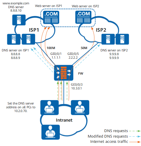
As shown in Figure 1, an enterprise rents links from both ISP1 and ISP2. The bandwidth of ISP1 link is 100M, and that of ISP2 link is 50M. The DNS server addresses of ISP1 are 8.8.8.8 and 8.8.8.9, and the DNS server addresses of ISP2 are 9.9.9.8 and 9.9.9.9. In normal cases, the clients of intranet users are configured with the same DNS server address. In normal cases, the clients of intranet users are configured with the same DNS server address. In normal cases, the clients of intranet users are configured with the same DNS server address. This case assumes that the DNS server address is 10.2.0.70.
The enterprise requires that the Internet access traffic of intranet users residing on network segment 10.3.0.0/24 can be distributed to ISP1 and ISP2 links in the ratio of 2:1 to ensure that the links are made full use of but not congested to improve users' Internet access experience.
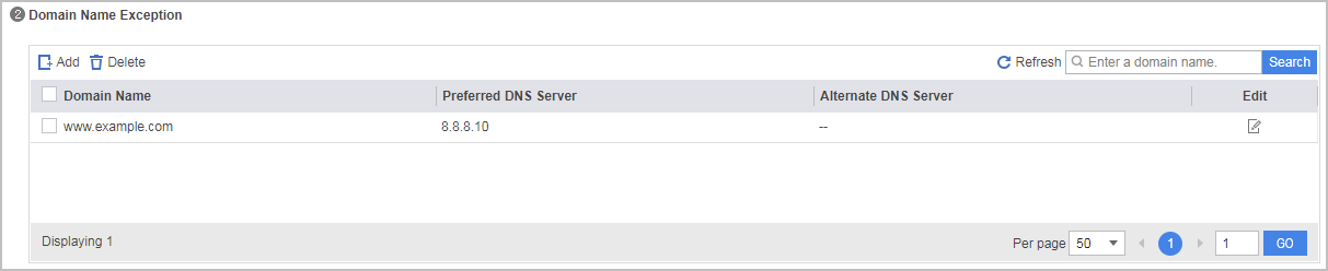
When intranet users access domain name www.example.com, FW does not perform DNS transparent proxying, but the Web server address of the domain name must be resolved by the specified DNS server (8.8.8.10).
When one link is overloaded (the threshold is 90%), follow-up traffic will be forwarded on the other link.
Configuration Roadmap
Configure the transparent proxy function on the FW to distribute DNS query messages from intranet users in the ratio of 2:1 to the DNS servers on ISP1 and ISP2 networks. When processing DNS query messages, the DNS transparent proxy function replaces the destination addresses of the messages with the DNS server address bound to the outbound interface. The selection of the outbound interface depends on the intelligent uplink selection function. Because the enterprise requires that the Internet access traffic can be distributed in the ratio of 2:1 to both links, you need to set the intelligent uplink selection mode to load balancing by link bandwidth. In the example, global route selection policies are configured. To ensure that the Internet access traffic is directly forwarded to the Web server on the ISP network of the destination address without taking a detour on other ISP networks, you need to configure ISP address database link selection.
- Optional: Configure the health check function. Configure a health check respectively for ISP1 and ISP2.
Set the interface IP address, security zone, gateway, bandwidth, and overload protection threshold, and apply the health check respectively on the interfaces.
Configure ISP link selection function. Make two ISP address files, isp1.csv and isp2.csv, and upload the two ISP address files to the FW.
Configure DNS transparent proxy. Bind the DNS server address on the outbound interface, specify the DNS server addresses requiring DNS transparent proxy, and specify the domain names to be excluded.
Configuring a global route selection policy. Set the intelligent uplink selection mode to load balancing by link bandwidth and configure the outbound interfaces on the FW connecting to ISP1 and ISP2 as intelligent uplink selection member interfaces.
Configure a basic security policy to allow intranet users to access the Internet.

This example focuses on the configuration related to intelligent uplink selection. Configure other data such as NAT based on the actual networking.
In this scenario, whether the traffic can be switched over due to overload depends on the DNS resolution result of the DNS transparent proxy.
Procedure
- Configure the link health check function for ISP1 and ISP2 links.
Choose , click Add in Health Check List, and perform the following configurations:
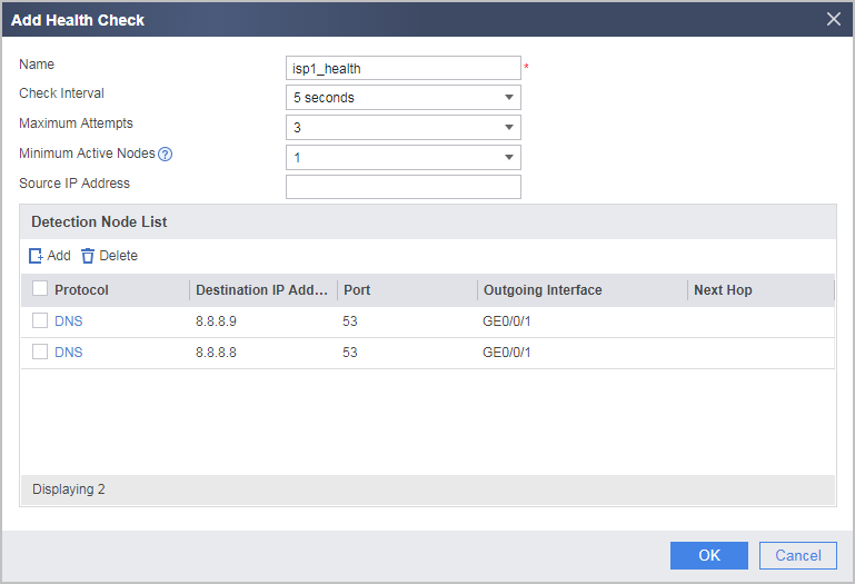
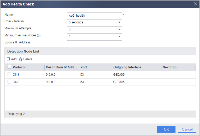
When the DNS transparent proxy function and the intelligent uplink selection function are used together and also when the health check of the DNS transparent proxy and the health check on the intelligent uplink selection interface both need to be enabled, the destination address for health check on the intelligent uplink selection interface must be set to the DNS server address bound to the interface and the detection protocol must be set to DNS. This is to ensure that the two health check results are the same and the interface link can always support the DNS proxy when the interface link is normal, preventing service access failures caused by DNS request failures.
If the state remains down after the health check configuration is complete, check the health check configuration.
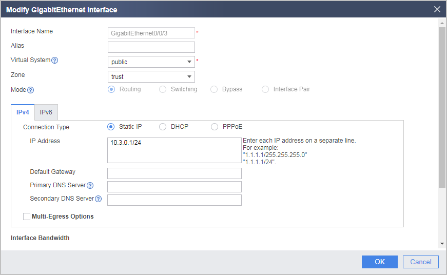
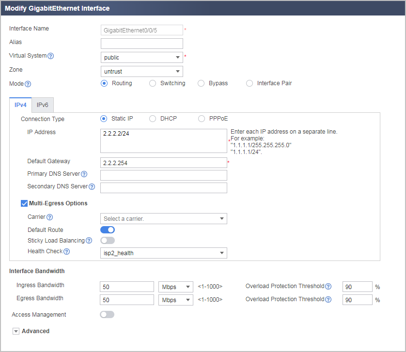
- Set the interface IP address, security zone, gateway, bandwidth, and overload protection threshold, and apply the health check respectively on the interfaces.
Choose , click
 in the row where the interface to be configured resides, and perform the following operations: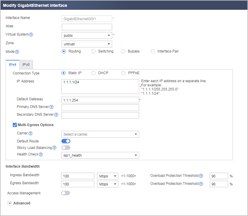
- Configure DNS transparent proxy.
- Choose , click the Transparent DNS Proxy tab, and perform the following configurations:
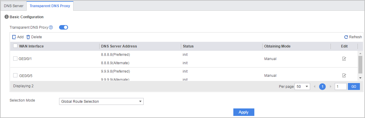
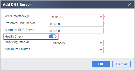
When the interface is bound to the DNS server, enable Health Check.
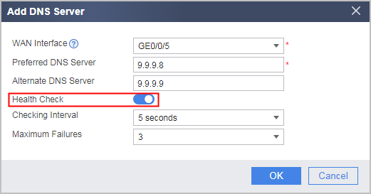
- Click Apply.
- When intranet users access www.example.com, DNS transparent proxy is not performed. However, the specified DNS server (8.8.8.10) should parse the corresponding web server address.
- Configure a DNS transparent proxy policy.
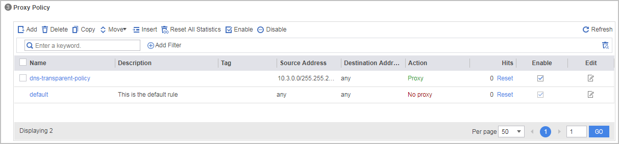
- Choose , click the Transparent DNS Proxy tab, and perform the following configurations:
- Configure ISP link selection function.
- Choose , click the Carrier Address Library tab, and upload the ISP address files to FW.

- Choose , click Add, and configure ISP link selection function.

- Choose , click the Carrier Address Library tab, and upload the ISP address files to FW.
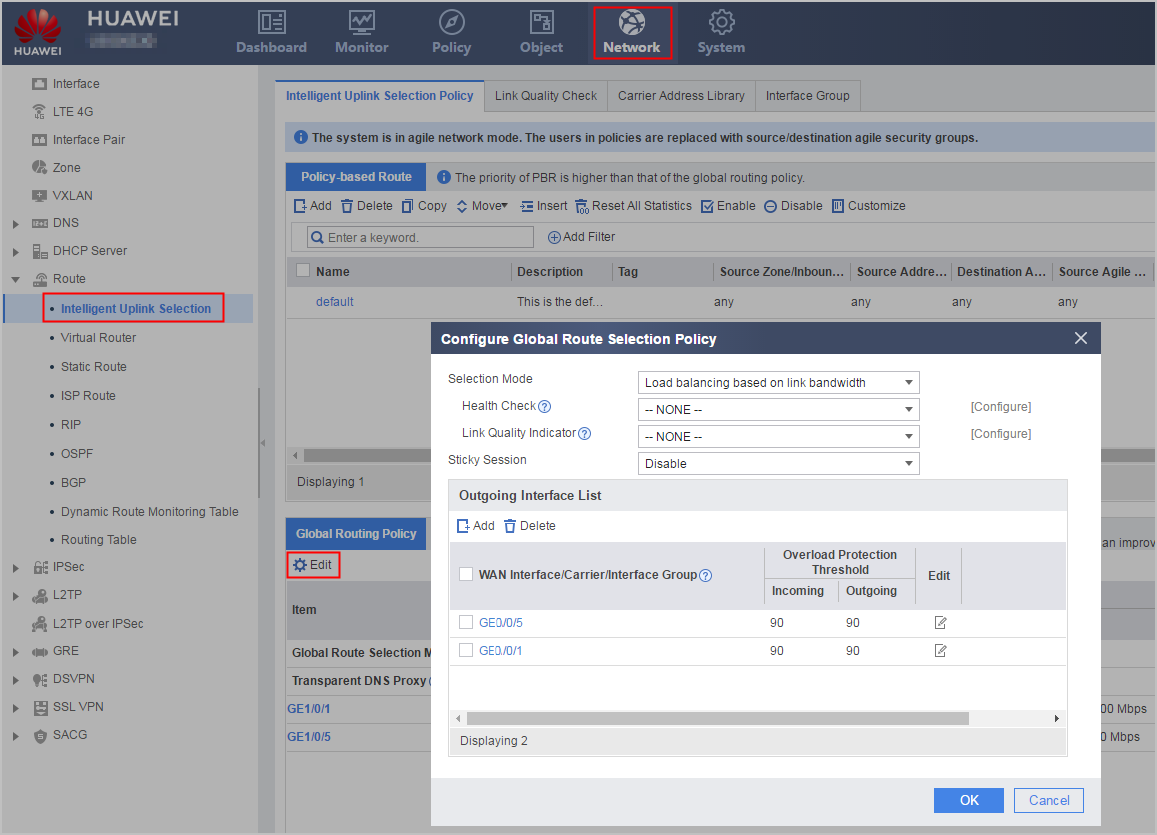
- Configure a global route selection policy, set load balancing based on link bandwidth, and add GigabitEthernet 0/0/1 and GigabitEthernet0/0/5 to the outgoing interface list.
Choose . In the Global Routing Policy area, click Edit.
- Configure security policies.
Choose .
Click Add Security Policy and set the following parameters to configure a security policy from Trust the zone to the Untrust zone to permit service packets. Then click OK.
Name
service
Source zone
trust
Destination zone
untrust
Source address/region
10.3.0.0/24
Action
Permit
Configuration Scripts
#
 isp name isp1 set filename isp1.csv
 isp name isp2 set filename isp2.csv
#
healthcheck enable
healthcheck name isp1_health
 destination 8.8.8.8 interface GigabitEthernet 0/0/1  protocol dns
 destination 8.8.8.9 interface GigabitEthernet 0/0/1  protocol dns
healthcheck name isp2_health
 destination 9.9.9.8 interface GigabitEthernet 0/0/5  protocol dns
 destination 9.9.9.9 interface GigabitEthernet 0/0/5  protocol dns
#
interface GigabitEthernet 0/0/1
 ip address 1.1.1.1 255.255.255.0
 healthcheck isp1_health
 gateway 1.1.1.254
 bandwidth ingress 100000 threshold 90
 bandwidth egress 100000 threshold 90
#
interface GigabitEthernet 0/0/5
 ip address 2.2.2.2 255.255.255.0
 healthcheck isp2_health
 gateway 2.2.2.254
 bandwidth ingress 50000 threshold 90
 bandwidth egress 50000 threshold 90
#
interface GigabitEthernet 0/0/3
 ip address 10.3.0.1 255.255.255.0
#
firewall zone trust
 set priority 85
 add interface GigabitEthernet 0/0/3
#
firewall zone untrust
 set priority 5
 add interface GigabitEthernet 0/0/1
 add interface GigabitEthernet 0/0/5
#
 ip route-isp isp1 interface GigabitEthernet 0/0/1 nexthop 1.1.1.254
 ip route-isp isp2 interface GigabitEthernet 0/0/5 nexthop 2.2.2.254
#
security-policy
 rule name service
  source-zone trust
  destination-zone untrust
  source-address 10.3.0.0 mask 255.255.255.0
  action permit
#
multi-interface
 mode proportion-of-bandwidth
 add interface GigabitEthernet 0/0/1
 add interface GigabitEthernet 0/0/5
#
dns-transparent-policy
 rule name dns-transparent-policy
  source-address 10.3.0.0 mask 255.255.255.255
  action tpdns
 dns transparent-proxy enable
 dns server bind interface GigabitEthernet 0/0/1 preferred 8.8.8.8 alternate 8.8.8.9 health-check enable
 dns server bind interface GigabitEthernet 0/0/5 preferred 9.9.9.8 alternate 9.9.9.9 health-check enable
 dns transparent-proxy exclude domain www.example.com server preferred 8.8.8.10
 mode based-on-multi-interface
#
return