Understanding VLANs
This section describes the virtual local area network (VLAN) mechanism.
VLAN Frame Format
The IEEE 802.1q standard modifies the Ethernet frame format by adding a 4-byte 802.1q tag between the source MAC address and the protocol type fields, as shown in Figure 1.
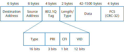
An 802.1q tag contains the following fields:
Type field: a 16-bit frame type. The value 0x8100 indicates an 802.1q tagged frame, which is discarded by devices that do not support the 802.1q standard.
PRI field: a 3-bit priority value of a frame. The value ranges from 0 to 7. The greater the value, the higher the priority. If a switch is blocked, the switch preferentially forwards packets with high priorities.
Canonical format indicator (CFI) field: This field is 1 bit long. The value 1 indicates the non-canonical format, and the value 0 indicates the canonical format.
VID field: specifies the ID of a VLAN to which a frame belongs. This field is 12 bits long.
Link Types
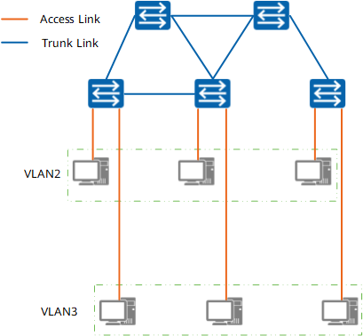
VLAN links are classified into the following types:
Port Types
Ports only on some devices can identify VLAN frames defined in 802.1q. Based on their ability of identifying VLAN frames, the ports are classified into the following types:
Access ports
Access ports are switch ports that connect hosts only along access links. An access port has the following characteristics:- Only allows frames tagged with access port PVIDs to pass through. A PVID is a default VLAN ID.
- Adds the port PVID to untagged frames that it receives.
- Sends untagged Ethernet frames to the peer device.
Trunk ports
Trunk ports connect a local switch to other switches. In other words, trunk ports can only connect to trunk links. A trunk port has the following characteristics:- Allows tagged frames of many VLANs to pass through.
- Only removes a tag with a default VLAN ID from a frame before sending the frame.
Hybrid ports
Hybrid ports are switch ports that connect a local switch to hosts and to other switches. Hybrid ports can be connected to both access and trunk links. A hybrid port allows tagged frames of different VLANs to pass through and removes tags from some VLAN frames before forwarding the frames.
VLAN Classification
VLANs can be classified into the following types:
Port-based VLANs
A computer belongs to a VLAN that is connected to a network device port on the computer. This method allows hosts to be easily grouped into VLANs. If a host of a VLAN is moved to another place, the VLAN needs to be reconfigured.
MAC address-based VLANs
Devices are allocated to VLANs based on MAC addresses of network interface cards. VLAN settings remain even if hosts are moved to other places. All hosts within a VLAN must be configured.
Network layer protocol-based VLANs
Devices are allocated to VLANs based on network layer protocols. For example, hosts running IP are grouped into a VLAN, and hosts running IPX are grouped into another VLAN.
The FW supports only port-based VLANs.
VLAN Communication Principles
To help improve frame processing efficiency, frames are tagged when being processed within a device.

The FW processes untagged STP packets in the same way as it processes untagged packets of other types.
The device processes frames based on the type of ports that receive the frames.
Port Type |
Processing a Received Frame |
Processing a Frame to Be Sent |
|---|---|---|
Access port |
|
Removes the PVID from the frame before sending it. |
Trunk port |
|
Checks the VLAN attribute of the port:
|
Hybrid port |
NOTE:
Trunk and hybrid ports use the same rules to process received data frames. |
Checks the VLAN attribute of the port:
NOTE:
If a hybrid port permits untagged frames, the hybrid port removes the VLAN Tag field the same as the PVID Tag field from a frame before sending it. If a hybrid port permits tagged frames, the hybrid port still removes the VLAN Tag field the same as the PVID Tag field from a frame before sending it. |
Intra-VLAN Communication
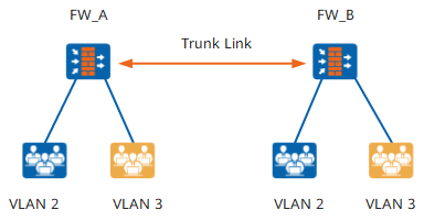
Hosts on a VLAN in the same area can directly communicate with each other. Hosts on the same VLAN but in different areas (with multiple devices between them) can communicate with each other using trunk links.
Figure 3 shows that hosts in the same department of an enterprise communicate with each other across two FWs. Each department belongs to a specific VLAN. You can configure trunk links to isolate service data of different departments to ensure data communication within a department.
Inter-VLAN Communication
Hosts of different VLANs use VLAN interfaces or Ethernet subinterfaces to communicate with each other.
Inter-VLAN communication using VLAN interfaces
VLAN interfaces function as Layer-3 physical interfaces to implement Layer-3 functions, such as IP address settings and inter-VLAN data communication.
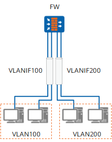
Figure 5 shows hosts of two departments attached to a FW. Hosts of one department belong to VLAN100, and hosts of the other department belong to VLAN200. You can configure a VLAN interface for each VLAN on the FW to allow hosts of the two departments to communicate with each other.
Note the following issues:- Layer-2 Ethernet interfaces connect the FW to PCs and are added to separate VLANs.
- Each interface on the FW can be connected to a single PC, which causes low data transmission efficiency.
Inter-VLAN communication using Ethernet subinterfaces
Unlike VLAN interfaces, Ethernet subinterfaces on a switch connect multiple PCs to a single interface of a FW to implement inter-VLAN communication.
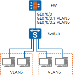
Figure 4 shows hosts of two departments attached to a FW. Hosts in one department belong to VLAN5, and host in the other department belong to VLAN6. You can configure two subinterfaces on a single physical interface and add these subinterfaces to separate VLANs. This approach allows VLANs to communicate with each other using a single physical interface on a FW.
The configuration requirements are as follows:Create two subinterfaces on an Ethernet interface that connects the FW to the switch and add a subinterface to VLAN5 and the other to VLAN6 to enable the two VLANs to communicate with each other.
- Configure 802.1Q encapsulation and assign an IP address to each subinterface.
- Change the type of the Ethernet interface that connects the switch to the FW from access to trunk or hybrid to permit packets from VLAN5 and VLAN6.
Inter-VLAN communication using Layer-2 Ethernet subinterfaces
Inter-VLAN communication through VLANIF interfaces or Layer-3 Ethernet subinterfaces applies only when hosts of VLANs are located in different network segment. When the hosts of VLANs are located in the same network segment without a conflict, inter-VLAN communication can be implemented through Layer-2 Ethernet subinterfaces.
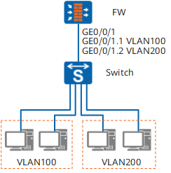
As shown in Figure 6, the intranet interface GigabitEthernet 0/0/1 on FW works in Layer-2 mode and it connects to two VLANs (VLAN100 and VLAN200). Two Layer-2 subinterfaces (GigabitEthernet 0/0/1.1 and GigabitEthernet 0/0/1.2) are configured at GigabitEthernet 0/0/1, and they are attributed to VLAN100 and VLAN200, respectively. Then Layer-2 subinterfaces GigabitEthernet 0/0/1.1 and GigabitEthernet 0/0/1.2 are added into the same VLAN (VLAN300, for example). The following uses VLAN100-to-VLAN200 access to show how FW processes packets.
FW receives packets from VLAN100 hosts through GigabitEthernet 0/0/1.1, strips VLAN tags from the packets, and broadcasts the packets in VLAN200. After finding the destination host in VLAN200, the device forwards the packets through GigabitEthernet 0/0/1.2 with a VLAN tag (VLAN200).