CLI Example: Applying a VXLAN to a Data Center
The VXLAN feature is often used with hot standby, virtual system, and NAT features on a data center.
Networking Requirements
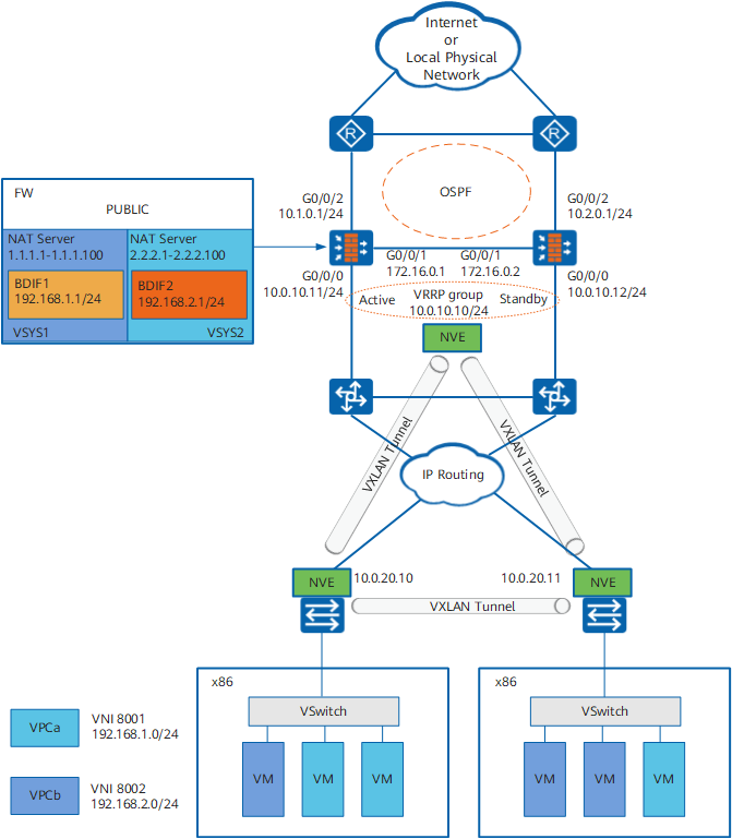
In a data center shown in Figure 1, VMs of one virtual private cloud (VPC) are deployed on different x86 servers. VXLAN-supported Layer-2 devices provide access and Layer-2 forwarding services for the VMs. The FWs act as VXLAN gateways and are responsible for network security between VPCs and between VPCs and physical networks. Route isolation is required between VPCs. Only public addresses are visible for external networks. For secure and stable networking, FWs must work in hot standby mode.
Security Zone |
Interface |
Description |
|---|---|---|
TRUST |
GigabitEthernet 0/0/0 |
Connecting to a VXLAN Layer-2 access device |
DMZ |
BDIF1 BDIF2 |
Outbound interfaces of VPCs where tenant VMs reside |
Virtual-if0 |
Outbound interface from a virtual system to the root system, equal to the BDIF interface for the root system |
|
GigabitEthernet 0/0/1 |
HRP heartbeat interface |
|
UNTRUST |
GigabitEthernet 0/0/2 |
Upstream interface connecting the device to the Internet or another physical network |
Virtual-if1 Virtual-if2 |
Interfaces connecting virtual systems to the root system, equal to GigabitEthernet 0/0/2 for virtual systems |
Configuration Roadmap
Connect two FWs to Layer-3 devices (OSPF configured) in the upstream direction and Layer-2 devices in active/standby mode (VRRP group configured) in the downstream direction.

Permit OSPF packets in the security policies for the interzone between the Local zone and the security zone where upstream interfaces reside. Otherwise, OSPF neighbor relationships cannot be set up.
Create the BD, VNI (VXLAN ID), and VXLAN tunnel. Set the source IP address of the NVE interface to the virtual IP address of the VRRP group.
Permit VXLAN packets in the security policies for the interzone between the Local zone and the security zone where VRRP group interfaces reside. Otherwise, VXLAN tunnels cannot be set up.
- Create a virtual system and associate the VNI and public IP address with the virtual system. Then, the BDIF interface is allocated to the virtual system along with the associated VNI.
Create a BDIF (VXLAN) interface, and set an IP address for the interface.
Set the same IP address on the standby device. Setting the same MAC address for both devices is recommended. Otherwise, services are interrupted for a short period during the switchover.
Configure NAT Server in the virtual system to map private IP addresses into public IP addresses.
- Configure a static route between the virtual system and root system.
- Configure the IP address of the BDIF interface as the VM gateway.
Configure the VXLAN Layer-2 access device. Set the peer IP address of VXLAN tunnel to the VRRP virtual IP address of the FW. Set up a VXLAN tunnel between VXLAN Layer-2 access devices.
Procedure
- Complete basic network configurations on FW_A.
# Configure IP addresses for interfaces.
<FW_A> system-view
[FW_A] interface GigabitEthernet 0/0/0
[FW_A-GigabitEthernet0/0/0] ip address 10.0.10.11 24
[FW_A-GigabitEthernet0/0/0] quit
[FW_A] interface GigabitEthernet 0/0/1
[FW_A-GigabitEthernet 0/0/1] ip address 172.16.0.1 24
[FW_A-GigabitEthernet 0/0/1] quit
[FW_A] interface GigabitEthernet 0/0/2
[FW_A-GigabitEthernet 0/0/2] ip address 10.1.0.1 24
[FW_A-GigabitEthernet 0/0/2] quit
# Assign interfaces to security zones.
[FW_A] firewall zone trust
[FW_A-zone-trust] add interface GigabitEthernet 0/0/0
[FW_A-zone-trust] quit
[FW_A] firewall zone dmz
[FW_A-zone-dmz] add interface GigabitEthernet 0/0/1
[FW_A-zone-dmz] add interface Virtual-if0
[FW_A-zone-dmz] quit
[FW_A] firewall zone untrust
[FW_A-zone-untrust] add interface GigabitEthernet 0/0/2
[FW_A-zone-untrust] quit
# Configure OSPF and import a static route.
[FW_A] ospf 10
[FW_A-ospf-10] import-route static
[FW_A-ospf-10] area 0
[FW_A-ospf-10-area-0.0.0.0] network 10.1.0.0 0.0.0.255
[FW_A-ospf-10-area-0.0.0.0] quit
[FW_A-ospf-10] quit
- Configure hot standby on FW_A.
# Configure a VGMP group on FW_A to monitor the upstream interface and configure a VRRP group on the downstream interface.
# Configure a VGMP group to monitor the upstream service interface.
[FW_A] hrp track interface GigabitEthernet 0/0/2
# Configure VRRP group 1 on downstream service interface GE0/0/0 and set the VRRP group status to active.
[FW_A] interface GigabitEthernet 0/0/0
[FW_A-GigabitEthernet0/0/0] vrrp vrid 1 virtual-ip 10.0.10.10 active
[FW_A-GigabitEthernet0/0/0] quit
# Configure the function of adjusting the OSPF cost based on VGMP status.
[FW_A] hrp adjust ospf-cost enable# Enable automatic backup of static routes.
[FW_A] hrp auto-sync config static-route# Specify the heartbeat interface and enable hot standby.
[FW_A] hrp interface GigabitEthernet 0/0/1 remote 172.16.0.2
[FW_A] hrp enable
- Configure hot standby on FW_B.
The configuration on FW_B is similar to that on FW_A except that:
- The IP addresses of interfaces on FW_B are different from those of interfaces on FW_A.
- The subnets to which FW_B advertises OSPF routes are different from those to which FW_A advertises OSPF routes.
- The status of VRRP group 1 on downstream service interfaces GE0/0/0 on FW_B must be set to standby.
- Configure the BD, VNI, and VXLAN tunnel.
Configure BDs and associate them with VNIs.
HRP_M[FW_A] bridge-domain 1
HRP_M[FW_A-bd-1] vxlan vni 8001
HRP_M[FW_A-bd-1] quit
HRP_M[FW_A] bridge-domain 2
HRP_M[FW_A-bd-2] vxlan vni 8002
HRP_M[FW_A-bd-2] quit
Set up a VXLAN tunnel and set the source address to the VRRP virtual IP address.
HRP_M[FW_A] interface nve 1
HRP_M[FW_A-Nve1] source 10.0.10.10
HRP_M[FW_A-Nve1] vni 8001 head-end peer-list 10.0.20.10 10.0.20.11
HRP_M[FW_A-Nve1] vni 8002 head-end peer-list 10.0.20.10 10.0.20.11
HRP_M[FW_A-Nve1] quit
- Create virtual systems and allocate VNIs and public addresses.
HRP_M[FW_A] vsys enable
HRP_M[FW_A] vsys name vsys1
HRP_M[FW_A-vsys-vsys1] assign global-ip 1.1.1.1 1.1.1.100 exclusive
HRP_M[FW_A-vsys-vsys1] assign vni 8001
HRP_M[FW_A-vsys-vsys1] quit
HRP_M[FW_A] vsys name vsys2
HRP_M[FW_A-vsys-vsys2] assign global-ip 2.2.2.2 2.2.2.100 exclusive
HRP_M[FW_A-vsys-vsys2] assign vni 8002
HRP_M[FW_A-vsys-vsys2] quit
- Create BDIF interfaces and set IP addresses for the interfaces.
If a BDIF interface already has an IP address when a virtual system is created, the IP address will be deleted.
HRP_M[FW_A] interface vbdif1
HRP_M[FW_A-Vbdif1] ip address 192.168.1.1 255.255.255.0
HRP_M[FW_A-Vbdif1] quit
HRP_M[FW_A] interface vbdif2
HRP_M[FW_A-Vbdif2] ip address 192.168.2.1 255.255.255.0
HRP_M[FW_A-Vbdif2] quit
- Configure static routes for the root system.
In this example, the IP address of the interface on the downstream device is 10.0.10.1.
HRP_M[FW_A] ip route-static 1.1.1.0 255.255.255.0 vpn-instance vsys1
HRP_M[FW_A] ip route-static 2.2.2.0 255.255.255.0 vpn-instance vsys2
HRP_M[FW_A] ip route-static 10.0.20.0 255.255.255.0 10.0.10.1
- Configure a security policy for the root system.
# Permit VXLAN packets.
HRP_M[FW_A] security-policy
HRP_M[FW_A-policy-security] rule name vxlan
HRP_M[FW_A-policy-security-rule-vxlan] source-zone trust
HRP_M[FW_A-policy-security-rule-vxlan] source-zone local
HRP_M[FW_A-policy-security-rule-vxlan] destination-zone trust
HRP_M[FW_A-policy-security-rule-vxlan] destination-zone local
HRP_M[FW_A-policy-security-rule-vxlan] destination-address 10.0.0.0 mask 255.255.0.0
HRP_M[FW_A-policy-security-rule-vxlan] service vxlan
HRP_M[FW_A-policy-security-rule-vxlan] action permit
HRP_M[FW_A-policy-security-rule-vxlan] quit
# Permit OSPF packets.
HRP_M[FW_A-policy-security] rule name ospf
HRP_M[FW_A-policy-security-rule-ospf] source-zone untrust
HRP_M[FW_A-policy-security-rule-ospf] source-zone local
HRP_M[FW_A-policy-security-rule-ospf] destination-zone untrust
HRP_M[FW_A-policy-security-rule-ospf] destination-zone local
HRP_M[FW_A-policy-security-rule-ospf] destination-address 10.0.0.0 mask 255.0.0.0
HRP_M[FW_A-policy-security-rule-ospf] service ospf
HRP_M[FW_A-policy-security-rule-ospf] action permit
HRP_M[FW_A-policy-security-rule-ospf] quit
# Permit access from Internet users to VMs in the intranet after NAT is performed.
HRP_M[FW_A-policy-security] rule name 1_in
HRP_M[FW_A-policy-security-rule-1_in] source-zone untrust
HRP_M[FW_A-policy-security-rule-1_in] destination-zone dmz
HRP_M[FW_A-policy-security-rule-1_in] destination-address 1.1.1.0 mask 255.255.255.0
HRP_M[FW_A-policy-security-rule-1_in] action permit
HRP_M[FW_A-policy-security-rule-1_in] quit
HRP_M[FW_A-policy-security] rule name 2_in
HRP_M[FW_A-policy-security-rule-2_in] source-zone untrust
HRP_M[FW_A-policy-security-rule-2_in] destination-zone dmz
HRP_M[FW_A-policy-security-rule-2_in] destination-address 2.2.2.0 mask 255.255.255.0
HRP_M[FW_A-policy-security-rule-2_in] action permit
HRP_M[FW_A-policy-security-rule-2_in] quit
# Permit intranet users to access the external network after NAT is performed.
HRP_M[FW_A-policy-security] rule name 1_out
HRP_M[FW_A-policy-security-rule-1_out] source-zone dmz
HRP_M[FW_A-policy-security-rule-1_out] destination-zone untrust
HRP_M[FW_A-policy-security-rule-1_out] source-address 1.1.1.0 mask 255.255.255.0
HRP_M[FW_A-policy-security-rule-1_out] action permit
HRP_M[FW_A-policy-security-rule-1_out] quit
HRP_M[FW_A-policy-security] rule name 2_out
HRP_M[FW_A-policy-security-rule-2_out] source-zone dmz
HRP_M[FW_A-policy-security-rule-2_out] destination-zone untrust
HRP_M[FW_A-policy-security-rule-2_out] source-address 2.2.2.0 mask 255.255.255.0
HRP_M[FW_A-policy-security-rule-2_out] action permit
HRP_M[FW_A-policy-security-rule-2_out] quit
HRP_M[FW_A-policy-security] quit
- Configure vsys1.
# Configure NAT Server.
HRP_M[FW_A] switch vsys vsys1
HRP_M<FW_A-vsys1> system-view
HRP_M[FW_A-vsys1] nat server to1 global 1.1.1.2 inside 192.168.1.2 unr-route
# Configure a static route.
HRP_M[FW_A-vsys1] ip route-static 0.0.0.0 0.0.0.0 public# Assign interfaces to security zones.
HRP_M[FW_A-vsys1] firewall zone dmz
HRP_M[FW_A-vsys1-zone-dmz] add interface Vbdif1
HRP_M[FW_A-vsys1-zone-dmz] quit
HRP_M[FW_A-vsys1] firewall zone untrust
HRP_M[FW_A-vsys1-zone-untrust] add interface Virtual-if1
HRP_M[FW_A-vsys1-zone-untrust] quit
# Permit access from Internet users to VMs in the intranet.
HRP_M[FW_A-vsys1] security-policy
HRP_M[FW_A-vsys1-policy-security] rule name in
HRP_M[FW_A-vsys1-policy-security-rule-in] source-zone untrust
HRP_M[FW_A-vsys1-policy-security-rule-in] destination-zone dmz
HRP_M[FW_A-vsys1-policy-security-rule-in] destination-address 192.168.1.0 mask 255.255.255.0
HRP_M[FW_A-vsys1-policy-security-rule-in] action permit
HRP_M[FW_A-vsys1-policy-security-rule-in] quit
# Allow intranet users to access the external network.
HRP_M[FW_A-vsys1-policy-security] rule name out
HRP_M[FW_A-vsys1-policy-security-rule-out] source-zone dmz
HRP_M[FW_A-vsys1-policy-security-rule-out] destination-zone untrust
HRP_M[FW_A-vsys1-policy-security-rule-out] source-address 192.168.1.0 mask 255.255.255.0
HRP_M[FW_A-vsys1-policy-security-rule-out] action permit
HRP_M[FW_A-vsys1-policy-security-rule-out] quit
HRP_M[FW_A-vsys1-policy-security] quit
HRP_M[FW_A-vsys1] quit
HRP_M<FW_A-vsys1> quit
- Configure vsys2.
# Configure NAT Server.
HRP_M[FW_A] switch vsys vsys2
HRP_M<FW_A-vsys2> system-view
HRP_M[FW_A-vsys2] nat server to1 global 2.2.2.2 inside 192.168.2.2 unr-route
# Configure a static route.
HRP_M[FW_A-vsys2] ip route-static 0.0.0.0 0.0.0.0 public# Assign interfaces to security zones.
HRP_M[FW_A-vsys2] firewall zone dmz
HRP_M[FW_A-vsys2-zone-dmz] add interface Vbdif2
HRP_M[FW_A-vsys2-zone-dmz] quit
HRP_M[FW_A-vsys2] firewall zone untrust
HRP_M[FW_A-vsys2-zone-untrust] add interface Virtual-if2
HRP_M[FW_A-vsys2-zone-untrust] quit
# Permit access from Internet users to VMs in the intranet.
HRP_M[FW_A-vsys2] security-policy
HRP_M[FW_A-vsys2-policy-security] rule name in
HRP_M[FW_A-vsys2-policy-security-rule-in] source-zone untrust
HRP_M[FW_A-vsys2-policy-security-rule-in] destination-zone dmz
HRP_M[FW_A-vsys2-policy-security-rule-in] destination-address 192.168.2.0 mask 255.255.255.0
HRP_M[FW_A-vsys2-policy-security-rule-in] action permit
HRP_M[FW_A-vsys2-policy-security-rule-in] quit
# Allow intranet users to access the external network.
HRP_M[FW_A-vsys2-policy-security] rule name out
HRP_M[FW_A-vsys2-policy-security-rule-out] source-zone dmz
HRP_M[FW_A-vsys2-policy-security-rule-out] destination-zone untrust
HRP_M[FW_A-vsys2-policy-security-rule-out] source-address 192.168.2.0 mask 255.255.255.0
HRP_M[FW_A-vsys2-policy-security-rule-out] action permit
HRP_M[FW_A-vsys2-policy-security-rule-out] quit
- Set IP addresses for BDIF interfaces on FW_B.
HRP_S<FW_B> system-view
HRP_S[FW_B] interface vbdif1
HRP_S[FW_B-Vbdif1] ip address 192.168.1.1 255.255.255.0
HRP_S[FW_B-Vbdif1] quit
HRP_S[FW_B] interface vbdif2
HRP_S[FW_B-Vbdif2] ip address 192.168.2.1 255.255.255.0
HRP_S[FW_B-Vbdif2] quit
- Optional: Set the same MAC address for the BDIF interfaces on FW_A and FW_B.
- Configure the routers, switches, and VXLAN Layer-2 access devices.
# Configure OSPF on the routers to advertise routes. For configuration commands, refer to the related documents of the routers.
# Add the three interfaces of the switches to the same VLANs accordingly. For configuration commands, refer to related documents of the switches.
# Configure VXLAN Layer-2 access and VXLAN tunnels on VXLAN Layer-2 access devices. For configuration commands, refer to the related documents of the devices.
Verification
Operation |
Queried Session Table |
|---|---|
Access from the VM at 192.168.1.2 in VPCa to a public IP address is successful. |
|
Access from the Internet to the NAT Server address (2.2.2.2) in VPCb is successful. |
|
Access from the VM at 192.168.1.2 in VPCa to the NAT Server address (2.2.2.2) in VPCb is successful. |
|
Shut down GigabitEthernet 0/0/2 on FW_A and repeat the preceding operations. The operations succeed. |
All the preceding session tables can be queried on FW_B. |
Configuration Scripts
FW_A |
FW_B |
|---|---|
# hrp enable hrp interface GigabitEthernet 0/0/1 remote 172.16.0.2 hrp adjust ospf-cost enable hrp auto-sync config static-route hrp track interface GigabitEthernet 0/0/2 # bridge-domain 1 vxlan vni 8001 # bridge-domain 2 vxlan vni 8002 # vsys enable # vsys name vsys1 1 assign global-ip 1.1.1.1 1.1.1.100 exclusive assign vni 8001 # vsys name vsys2 2 assign global-ip 2.2.2.1 2.2.2.100 exclusive assign vni 8002 # interface GigabitEthernet0/0/0 ip address 10.0.10.11 255.255.255.0 vrrp vrid 1 virtual-ip 10.0.10.10 active # interface GigabitEthernet 0/0/1 ip address 172.16.0.1 255.255.255.0 # interface GigabitEthernet 0/0/2 ip address 10.1.0.1 255.255.255.0 # interface Vbdif1 ip address 192.168.1.1 255.255.255.0 # interface Vbdif2 ip address 192.168.2.1 255.255.255.0 # interface Nve1 source 10.0.10.10 vxlan statistic enable vni 8001 head-end peer-list 10.0.20.10 10.0.20.11 vni 8002 head-end peer-list 10.0.20.10 10.0.20.11 # firewall zone trust set priority 85 add interface GigabitEthernet0/0/0 # firewall zone untrust set priority 5 add interface GigabitEthernet 0/0/2 # firewall zone dmz set priority 50 add interface Virtual-if0 add interface GigabitEthernet 0/0/1 # ospf 1 import-route static area 0.0.0.0 network 10.1.0.0 0.0.0.255 # ip route-static 1.1.1.0 255.255.255.0 vpn-instance vsys1 ip route-static 2.2.2.0 255.255.255.0 vpn-instance vsys2 ip route-static 10.0.20.0 255.255.255.0 10.0.10.1 # security-policy rule name vxlan source-zone local source-zone trust destination-zone local destination-zone trust destination-address 10.0.0.0 mask 255.255.0.0 service vxlan action permit rule name ospf source-zone local source-zone untrust destination-zone local destination-zone untrust destination-address 10.0.0.0 mask 255.0.0.0 service ospf action permit rule name 1_in source-zone untrust destination-zone dmz destination-address 1.1.1.0 mask 255.255.255.0 action permit rule name 2_in source-zone untrust destination-zone dmz destination-address 2.2.2.0 mask 255.255.255.0 action permit rule name 1_out source-zone dmz destination-zone untrust source-address 1.1.1.0 mask 255.255.255.0 action permit rule name 2_out source-zone dmz destination-zone untrust source-address 2.2.2.0 mask 255.255.255.0 action permit # switch vsys vsys1 # interface Vbdif1 ip address 192.168.1.1 255.255.255.0 # firewall zone untrust set priority 5 add interface Virtual-if1 # firewall zone dmz set priority 50 add interface Vbdif1 # security-policy rule name in source-zone untrust destination-zone dmz destination-address 192.168.1.0 mask 255.255.255.0 action permit rule name out source-zone dmz destination-zone untrust source-address 192.168.1.0 mask 255.255.255.0 action permit # ip route-static 0.0.0.0 0.0.0.0 public # nat server to1 0 global 1.1.1.2 inside 192.168.1.2 unr-route # switch vsys vsys2 # interface Vbdif2 ip address 192.168.2.1 255.255.255.0 # firewall zone untrust set priority 5 add interface Virtual-if2 # firewall zone dmz set priority 50 add interface Vbdif2 # security-policy rule name in source-zone untrust destination-zone dmz destination-address 192.168.2.0 mask 255.255.255.0 action permit rule name out source-zone dmz destination-zone untrust source-address 192.168.2.0 mask 255.255.255.0 action permit # ip route-static 0.0.0.0 0.0.0.0 public # nat server to2 1 global 2.2.2.2 inside 192.168.2.2 unr-route # |
# hrp enable hrp interface GigabitEthernet 0/0/1 remote 172.16.0.1 hrp adjust ospf-cost enable hrp auto-sync config static-route hrp track interface GigabitEthernet 0/0/2 # bridge-domain 1 vxlan vni 8001 # bridge-domain 2 vxlan vni 8002 # vsys enable # vsys name vsys1 1 assign global-ip 1.1.1.1 1.1.1.100 exclusive assign vni 8001 # vsys name vsys2 2 assign global-ip 2.2.2.1 2.2.2.100 exclusive assign vni 8002 # interface GigabitEthernet0/0/0 ip address 10.0.10.12 255.255.255.0 vrrp vrid 1 virtual-ip 10.0.10.10 standby # interface GigabitEthernet 0/0/1 ip address 172.16.0.2 255.255.255.0 # interface GigabitEthernet 0/0/2 ip address 10.2.0.1 255.255.255.0 # interface Vbdif1 ip address 192.168.1.1 255.255.255.0 # interface Vbdif2 ip address 192.168.2.1 255.255.255.0 # interface Nve1 source 10.0.10.10 vxlan statistic enable vni 8001 head-end peer-list 10.0.20.10 10.0.20.11 vni 8002 head-end peer-list 10.0.20.10 10.0.20.11 # firewall zone trust set priority 85 add interface GigabitEthernet0/0/0 # firewall zone untrust set priority 5 add interface GigabitEthernet 0/0/2 # firewall zone dmz set priority 50 add interface Virtual-if0 add interface GigabitEthernet 0/0/1 # ospf 1 import-route static area 0.0.0.0 network 10.2.0.0 0.0.0.255 # ip route-static 1.1.1.0 255.255.255.0 vpn-instance vsys1 ip route-static 2.2.2.0 255.255.255.0 vpn-instance vsys2 ip route-static 10.0.20.0 255.255.255.0 10.0.10.1 # security-policy rule name vxlan source-zone local source-zone trust destination-zone local destination-zone trust destination-address 10.0.0.0 mask 255.255.0.0 service vxlan action permit rule name ospf source-zone local source-zone untrust destination-zone local destination-zone untrust destination-address 10.0.0.0 mask 255.0.0.0 service ospf action permit rule name 1_in source-zone untrust destination-zone dmz destination-address 1.1.1.0 mask 255.255.255.0 action permit rule name 2_in source-zone untrust destination-zone dmz destination-address 2.2.2.0 mask 255.255.255.0 action permit rule name 1_out source-zone dmz destination-zone untrust source-address 1.1.1.0 mask 255.255.255.0 action permit rule name 2_out source-zone dmz destination-zone untrust source-address 2.2.2.0 mask 255.255.255.0 action permit # switch vsys vsys1 # interface Vbdif1 ip address 192.168.1.1 255.255.255.0 # firewall zone untrust set priority 5 add interface Virtual-if1 # firewall zone dmz set priority 50 add interface Vbdif1 # security-policy rule name in source-zone untrust destination-zone dmz destination-address 192.168.1.0 mask 255.255.255.0 action permit rule name out source-zone dmz destination-zone untrust source-address 192.168.1.0 mask 255.255.255.0 action permit # ip route-static 0.0.0.0 0.0.0.0 public # nat server to1 0 global 1.1.1.2 inside 192.168.1.2 unr-route # switch vsys vsys2 # interface Vbdif2 ip address 192.168.2.1 255.255.255.0 # firewall zone untrust set priority 5 add interface Virtual-if2 # firewall zone dmz set priority 50 add interface Vbdif2 # security-policy rule name in source-zone untrust destination-zone dmz destination-address 192.168.2.0 mask 255.255.255.0 action permit rule name out source-zone dmz destination-zone untrust source-address 192.168.2.0 mask 255.255.255.0 action permit # ip route-static 0.0.0.0 0.0.0.0 public # nat server to2 1 global 2.2.2.2 inside 192.168.2.2 unr-route # |