CLI: Example for Configuring Communication Between Different Network Segments Through VXLAN Tunnels
This section describes how to configure a VXLAN tunnel in static mode when the FW serves as a Layer 3 VXLAN gateway.
Networking Requirements
As shown in Figure 1, an enterprise has its Host1 and Host2 deployed at different locations of the data center, and the FW serves as a Layer 3 VXLAN gateway of the data center. The enterprise attempts to enable mutual communication between Host1 and Host2 through VXLAN tunnels.
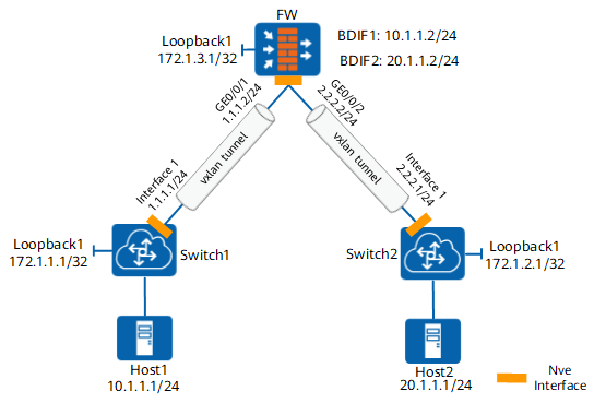
Configuration Roadmap
- Configure BDs and BDIF interfaces.
The FW serves as a Layer 3 VXLAN gateway and needs to have VXLAN tunnels established with both Switch1 and Switch2. Therefore, two BDs and two BDIF interfaces shall be created.
- Configure the NVE tunnel interface.
The FW needs to use only one NVE interface to establish VXLAN tunnels with both Switch1 and Switch2.
Procedure
- Complete basic network configurations on the FW.
# Set IP addresses of the interfaces.
<FW> system-view
[FW] interface GigabitEthernet 0/0/1
[FW-GigabitEthernet 0/0/1] ip address 1.1.1.2 24
[FW-GigabitEthernet 0/0/1] quit
[FW] interface GigabitEthernet 0/0/2
[FW-GigabitEthernet 0/0/2] ip address 2.2.2.2 24
[FW-GigabitEthernet 0/0/2] quit
# Assign the interfaces to security zones.
[FW] firewall zone untrust
[FW-zone-untrust] add interface GigabitEthernet 0/0/1
[FW-zone-untrust] add interface GigabitEthernet 0/0/2
[FW-zone-untrust] quit
- Configure BDs and BDIF interfaces.
# Configure BDs and specify VNIs associated with the BDs.
[FW] bridge-domain 1
[FW-bd-1] vxlan vni 10
[FW-bd-1] quit
[FW] bridge-domain 2
[FW-bd-2] vxlan vni 20
[FW-bd-2] quit
# Set IP addresses of the BDIF interfaces.
[FW] interface vbdif 1
[FW-Vbdif1] ip address 10.1.1.2 255.255.255.0
[FW-Vbdif1] quit
[FW] interface vbdif 2
[FW-Vbdif2] ip address 20.1.1.2 255.255.255.0
[FW-Vbdif2] quit
# Assign the BDIF interfaces to security zones.
[FW] firewall zone trust
[FW-zone-trust] add interface vbdif 1
[FW-zone-trust] add interface vbdif 2
[FW-zone-trust] quit
- Configure an NVE interface.
[FW] interface loopback 1
[FW-LoopBack1] ip address 172.1.3.1 32
[FW-LoopBack1] quit
[FW] interface nve 1
[FW-Nve1] source 172.1.3.1
[FW-Nve1] vni 10 head-end peer-list 172.1.1.1
[FW-Nve1] vni 20 head-end peer-list 172.1.2.1
- Configure OSPF.
[FW] ospf 1
[FW-ospf-1] area 0
[FW-ospf-1-area-0.0.0.0] network 172.1.3.1 0.0.0.0
[FW-ospf-1-area-0.0.0.0] network 1.1.1.0 0.0.0.255
[FW-ospf-1-area-0.0.0.0] network 2.2.2.0 0.0.0.255
[FW-ospf-1-area-0.0.0.0] quit
[FW-ospf-1] quit
- Configure a security policy to permit VXLAN packets.
[FW] security-policy
[FW-policy-security] rule name vxlan
[FW-policy-security-rule-vxlan] source-zone local
[FW-policy-security-rule-vxlan] source-zone untrust
[FW-policy-security-rule-vxlan] destination-zone local
[FW-policy-security-rule-vxlan] destination-zone untrust
[FW-policy-security-rule-vxlan] source-address 172.1.0.0 mask 255.255.0.0
[FW-policy-security-rule-vxlan] service vxlan
[FW-policy-security-rule-vxlan] action permit
[FW-policy-security-rule-vxlan] quit
- Configure Switch1 and Switch2. For details, see the switch product documentation.
- Configure OSPF on the switches to advertise routes.
- Configure tunnel information of Layer 2 VXLAN gateways.
Verification
- Run the display vxlan tunnel command on the FW. The VXLAN tunnels have been established.
- Host1 can properly access Host2.
Configuration Scripts
#
sysname FW
#
bridge-domain 1
 vxlan vni 10
#
bridge-domain 2
 vxlan vni 20
#
interface GigabitEthernet 0/0/1
 ip address 1.1.1.2 24
#
interface GigabitEthernet 0/0/2
 ip address 2.2.2.2 24
#
interface LoopBack1
 ip address 172.1.3.1 255.255.255.255
#
interface Vbdif1
 ip address 10.1.1.2 255.255.255.0
#
interface Vbdif2
 ip address 20.1.1.2 255.255.255.0
#
interface Nve1
 source 172.1.3.1
 vxlan statistic enable
 vni 10 head-end peer-list 172.1.1.1
 vni 20 head-end peer-list 172.1.2.1
#
firewall zone trust
 set priority 85
 add interface Vbdif1
 add interface Vbdif2
#
firewall zone untrust
 set priority 5
 add interface GigabitEthernet 0/0/1
 add interface GigabitEthernet 0/0/2
#
ospf 1
 area 0.0.0.0
  network 172.1.3.1 0.0.0.0
  network 1.1.1.0 0.0.0.255
  network 2.2.2.0 0.0.0.255
#
security-policy
 rule name vxlan
  source-zone local
  source-zone untrust
  destination-zone local
  destination-zone untrust
  source-address 172.1.0.0 mask 255.255.0.0
  service vxlan
  action permit