Understanding NTP
This section describes the NTP principles.
Principles of NTP
Figure 1 shows the principles of NTP. FW_A and FW_B are connected through a WAN. They both have their own system clocks. NTP implements automatic synchronization of their clocks.
Suppose:
Before the system clocks of FW_A and FW_B are synchronized, the clock of FW_A is set to 10:00:00 am and the clock of FW_B is set to 11:00:00 am.
FW_B functions as an NTP time server. That is, FW_A synchronizes its clock with that of FW_B.
One-way transmission of data packets between FW_A and FW_B takes one second.
Processing of data packets on the FW_A or the FW_B takes one second.
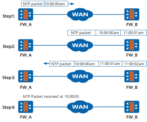
The process of synchronizing system clocks is as follows:
FW_A sends an NTP packet to FW_B. The packet carries the originating timestamp when it leaves FW_A, which is 10:00:00 am (T1).
When the NTP packet reaches FW_B, FW_B adds its receiving timestamp to the NTP packet, which is 11: 00:01 am (T2).
When the NTP packet leaves FW_B, FW_B adds its transmitting timestamp to the NTP packet, which is 11:00:02 am (T3).
When FW_A receives the response packet, it adds a new receiving timestamp to it, which is 10:00:03 am (T4).
FW_A uses the received information to calculate the following two important values:
Delay for the NTP message cycle: Delay = (T4 - T1) - (T3 - T2).
Offset of FW_A relative to FW_B: Offset = ((T2 - T1) + (T3 - T4))/2.
According to the delay and the offset, FW_A sets its own clock again to synchronize with the clock of FW_B.

The preceding example is only a simple description of the NTP operating principle. As described in RFC 1305, NTP uses a complex algorithm to ensure the precision of clock synchronization.
Network Architecture
As shown in Figure 2, the networking of NTP is composed of the primary time server, secondary time servers, clients, and interconnections in between.
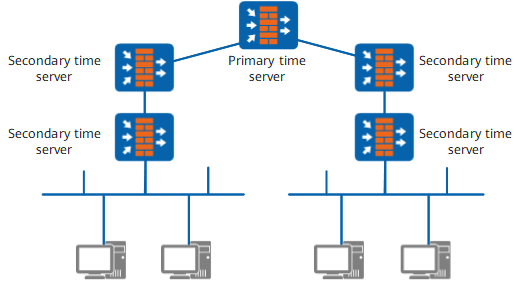
The primary time server is directly synchronized with a primary reference source which is usually a radio clock or Global Positioning System (GPS).
A secondary time server synchronizes its clock with the clock of the primary time server or another secondary time server on the network and transmits the time information to other hosts on the network through NTP.
Under normal circumstances, primary and secondary time servers on the synchronization subnet assume a hierarchical structure, with the primary server at the root and the secondary server at successive stratums toward the leaf node. The higher the stratum level is, the less accurate the clock.
Modes of NTP
The NTP supports the following working modes:
Unicast Client/Server Mode
In this mode, you need to configure only the client. The server needs to be configured with only one NTP primary clock.
Note that the client can be synchronized to the server but the server cannot be synchronized to the client.
After the configurations:
The client sends a synchronization request packet to the server, with the mode field being set to 3. The value 3 indicates the client mode.
Upon receiving the request packet, the server automatically works in the server mode and sends a response packet with the mode field being set to 4. The value 4 indicates the server mode.
After receiving the response packet, the client performs clock filtering and selection, and finally, is synchronized with the optimal server.
Kiss-o'-Death (KOD) packets provide useful information to a client and are used for status reporting and access control. When KOD is enabled at the server, the server may send packets with kiss codes DENY and RATE to the client.- When the client receives packet with kiss code DENY, the client demobilizes any associations with that server and stops sending packets to that server.
- When the client receives packet with kiss code RATE, the client immediately reduces its polling interval to that server and continues to reduce it each time it receives a RATE kiss code.
Peer Mode
In this mode, you need to configure NTP only on the symmetric active end. The symmetric active end and symmetric passive end can be synchronized with each other.
Note that the clock with a lower stratum is synchronized to the one with a higher stratum.
After the configurations:
The symmetric active end sends a synchronization request packet to the symmetric passive end with the mode field being set to 1. The value 1 indicates the symmetric active mode.
Upon receiving the request packet, the symmetric passive end automatically works in symmetric passive mode and sends a response packet with the mode field being set to 2. The value 2 indicates the symmetric passive mode.
Broadcast Mode
In this mode, you need to configure both the server and the client.
After the configurations:
The server periodically sends clock synchronization packets to the broadcast address 255.255.255.255.
The client senses broadcast packets from the server.
After receiving the first broadcast packet, to estimate the network delay, the client enables a temporary client/server model for exchanging messages with the remote server.
The client then works in broadcast client mode, and continues to sense the incoming broadcast packets to synchronize the local clock.
Multicast Mode
In this mode, you need to configure both the server and the client.
After the configurations:
The server periodically sends clock synchronization packets to the multicast address 224.0.1.1.
The client senses multicast packets from the server.
After receiving the first multicast packet, to estimate the network delay, the client enables a temporary client/server model for exchanging messages with the remote server.
The client works in multicast client mode, and continues to sense the incoming multicast packets to synchronize the local clock.
Manycast Mode
In this mode, you need to configure both the server and the client.
After the configurations, the following actions occur:
- The manycast client periodically sends clock synchronization packets manycast server with specified multicast address. By default, the multicast address is 224.0.1.1.
- The manycast server senses manycast packets from the manycast client and responds to the client with unicast packet.
- After receiving the first unicast packet by manycast client, to estimate the network delay, the client creates an ephemeral association with the server for exchanging unicast packets.
- The server works in manycast server mode, and continues to sense the incoming manycast packets.
Security mechanism of NTP
NTP provides two security mechanisms: access authority and NTP authentication to guarantee the network security.
Access Authority
The device protects local NTP services by setting access authority. This is a simple measure to ensure security.
The device provides four access authority levels. When an NTP access request message reaches the local end, the device matches it with the access authority from level 1 to level 4. The first matched authority level takes effect. The matching sequence is as follows:
- peer: indicates the minimum access authority. The remote end can perform time requests and control queries for the local NTP service. The local clock can also be synchronized with the clock of the remote server.
- server: indicates that the remote end can perform time requests and control queries for the local NTP service. The local clock, however, cannot be synchronized with the clock of the remote server.
- synchronization: indicates that the remote end can perform time requests only for the local NTP service.
- query: indicates the maximum access authority. The remote end can perform control queries only for the local NTP service.
Authentication
NTP authentication can be enabled on networks demanding high security.
When configuring NTP authentication, note the following rules:
- Configurations of NTP authentication on both the client and the server must be complete. Otherwise, the authentication does not take effect. If NTP authentication is enabled, you must configure the key and declare the key as reliable.
- Keys configured on the server and the client must be identical.