Web: Example for Configuring TCP Proxy
This section provides an example for configuring TCP proxy to implement TCP-layer isolation for data of different enterprise departments.
Networking Requirements
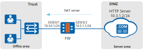
As shown in Figure 1, the FW serves as a TCP proxy. It is deployed between the office area and server area of the enterprise to proxy all TCP traffic sent from the office area and server area.
Moreover, to hide the real IP address of the server and simplify the routing configuration of the office area, the NAT server function needs to be configured on the FW to map server address 10.3.1.2:80 to 10.3.0.100:8080 so that users in the office area can access the server.
Procedure
- Set an IP address for each interface, assign interfaces to security zones, and complete basic parameter settings.
- Choose .
Click
 of GE0/0/1 and set the parameters as follows:
Zone
trust
IPv4
IP Address
10.3.0.1/24
- Click OK.
Repeat the preceding steps to configure interface GE0/0/2.
Zone
untrust
IPv4
IP Address
10.3.1.1/24
- Configure a security policy.
- Click Add and configure a security policy.
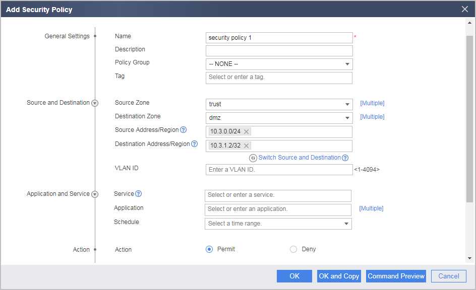
- Click Add and configure a security policy.
- Configure server mappings.
- Choose .
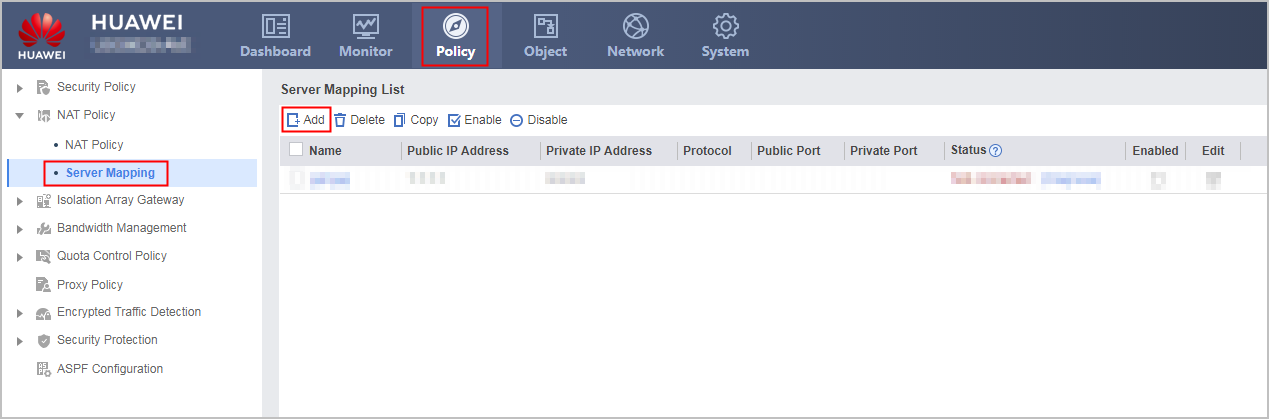
- Click Add to configure server mappings.
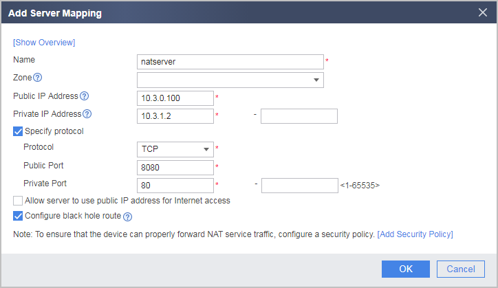
- Choose .
- Configure a proxy policy.
- Choose .
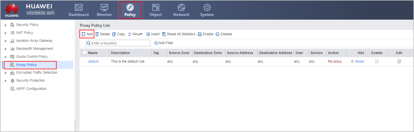
- Click Add and configure a proxy policy.
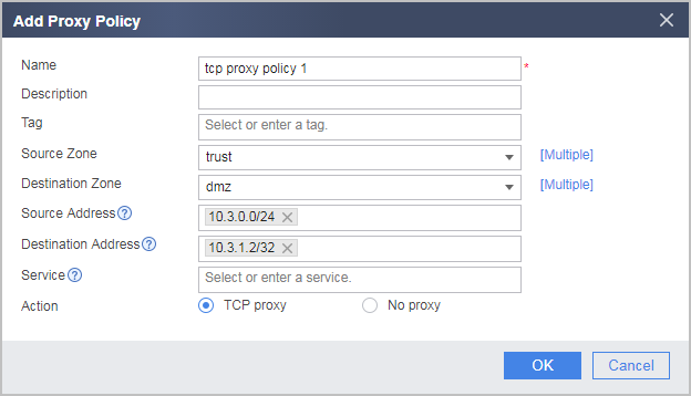

The destination address of the proxy policy should be configured to the private address of the server. This is because the FW that has the NAT server function configured matches a packet with the server-map table, translates the destination address of the packet into the private address of the server, and then matches the packet with the proxy policy.
- Choose .
Configuration Verification
- Users in the office area can access the server through address 10.3.0.100:8080.
Check the TCP proxy session table on the FW. The FW serves as the proxy for the TCP traffic sent from the office area to the server.
<FW> display tcp-proxy session table
 vsys: 0 10.3.0.2:51771--->10.3.1.2:80 Left:00:00:05 Age:2 down:0000 -->bytes: 997 <--: 715
Configuration Script
#
interface GigabitEthernet 0/0/1
 ip address 10.3.0.1 255.255.255.0
#
interface GigabitEthernet 0/0/2
 ip address 10.3.1.1 255.255.255.0
#
firewall zone trust
 add interface GigabitEthernet 0/0/1
#
firewall zone dmz
 add interface GigabitEthernet 0/0/2
#
nat server natserver protocol tcp global 10.3.0.100 8080 inside 10.3.1.2 www no-reverse unr-route
#
security-policy
 rule name "security policy 1"
  source-zone trust
  destination-zone dmz
  source-address 10.3.0.0 24
  destination-address 10.3.1.2 32
  action permit
 #
 proxy-policy
  rule name "tcp proxy policy 1"
   source-zone trust
   destination-zone dmz
   source-address 10.3.0.0 24
   destination-address 10.3.1.2 32
   action tcp-proxy