Routing Table and FIB Table
The routing table is used to select routes, and the Forwarding Information Base (FIB) is used to guide packet forwarding. Each router maintains one routing table and one FIB table at least.
Routes discovered by various routing protocols are stored in the routing table. According to the sources, the routes in the routing table are divided into the following types:
Directly connected route or interface route
The directly connected route, in another word, the interface route, refers to the route discovered by the link layer protocols.
Static route
The static route refers to the route manually configured by the network administrator.
Dynamic route
The dynamic route refers to the route dynamically discovered by dynamic routing protocols.
Each entry in the FIB table contains the physical or logical interface through which a packet is sent to a network segment or a host, and then it can reach the next router. Besides, the entry also indicates that the packet can be directly sent to a destination host in the directly connected network.
Routing Table
Each router maintains the protocol routing table for each protocol and a local core routing table (or routing management table).
Protocol routing table
A protocol routing table stores the routing information discovered by the protocol.
A routing protocol can import and advertise the routes that are discovered by other protocols. For example, if a router that runs the Open Shortest Path First (OSPF) protocol needs to use OSPF to advertise direct routes, static routes, or Intermediate System-Intermediate System (IS-IS) routes, the router must import the routes to the OSPF routing table.
Local core routing table
A router uses the local core routing table to store protocol routes and preferred routes. The router then delivers the preferred routes to the FIB table to guide the packets forwarding.
The router selects routes according to the priorities of protocols and costs in the routing table. You can run the display ip routing-table command to view the local core routing table of a router.

The FW that supports the Layer 3 Virtual Private Network (L3VPN) maintains a local core routing table for each VPN instance.
Contents of the Routing Table
In the FW, by running the display ip routing-table command, you can view the brief routing table of the router as below:
<FW> display ip routing-table
Route Flags: R - relay, D - download to fib
------------------------------------------------------------------------------
Routing Tables: Public
         Destinations : 8        Routes : 8

Destination/Mask  Proto  Pre  Cost   Flags NextHop        Interface

   0.0.0.0/0      Static 60   0      D     10.1.4.2        GigabitEthernet0/0/0
  10.1.1.0/24     Direct 0    0      D     10.1.1.1        GigabitEthernet0/0/1
  10.1.1.1/32     Direct 0    0      D     127.0.0.1       InLoopBack0
  10.1.4.0/30     OSPF   10   0      D     10.1.4.1        GigabitEthernet0/0/0
  10.1.4.1/32     Direct 0    0      D     127.0.0.1       InLoopBack0
  10.1.4.2/32     OSPF   10   0      D     10.1.4.2        GigabitEthernet0/0/0
  127.0.0.0/8     Direct 0    0      D     127.0.0.1       InLoopBack0
  127.0.0.1/32    Direct 0    0      D     127.0.0.1       InLoopBack0
A routing table has the following key entries:
- Destination address: is used to identify the destination IP address or the destination network address of an IP packet.
Network mask: is combined with the destination address to identify the address of the network segment where the destination host or router resides.
- The network address of the destination host or the router is obtained through the "AND" operation on the destination address and network mask. For example, if the destination address is 10.1.1.1 and the mask is 255.255.255.0, the address of the network where the host or the router resides is 10.1.1.0.
- The network mask is composed of several consecutive 1s. These 1s can be expressed either in the dotted decimal notation or in the number of consecutive 1s in the mask. For example, the network mask can be expressed either as 255.255.255.0 or as 24.
- Proto: indicates the protocol through which routes are learned.
- Pre: indicates the preference added to the IP routing table for a route. To the same destination, multiple routes with different next hops and outgoing interfaces exist. These routes may be discovered by different routing protocols, or they may just be the manually configured static routes. The route with the highest preference (the smallest value) is selected as the optimal route.
Cost: indicates the route cost. When multiple routes to the same destination have the same preference, the route with the smallest cost is selected as the optimal route.
Preference is used to compare the preferences of various routing protocols, while cost is used to compare the preferences of different routes of the same routing protocol.
- NextHop: indicates the IP address of the next router that an IP packet passes through.
- Interface: indicates the outgoing interface through which an IP packet is forwarded.
According to the destination, the routes can be divided into the following types:
- Subnet route: The destination is a subnet.
- Host route: The destination is a host.
In addition, based on whether the destination is directly connected to the router or not, routes fall into the following types:
- Direct route: The router is directly connected to the network in which the destination resides.
- Indirect route: The router is not directly connected to the network in which the destination resides.
You can set a default route to reduce the number of entries in the routing table. All the packets that fail to match entries in the routing table are forwarded through this default route. For example, in the preceding routing table, the route whose destination address is 0.0.0.0/0 is a default route.
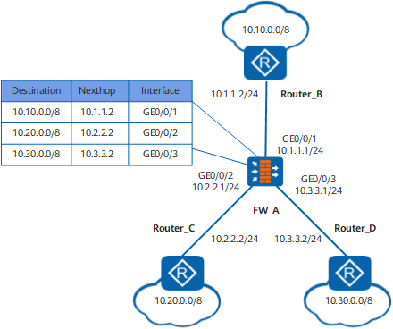
As shown in Figure 1, FW_A is connected with three networks, so it has three IP addresses and three physical interfaces. Figure 1 shows the routing table of FW_A.
Matching of FIB Table
After the route selection is complete, routers deliver the active routes in the routing table to the FIB table. When receiving a packet, routers search the FIB table for the optimal route to forward the packet.
The matching of the FIB table complies with the longest match. When searching the FIB table, routers perform the "AND" operation on the destination address in the packet and the network mask of each entry in the FIB table. routers then compare the result of the "AND" operation with the entries in the FIB table. According to the comparison, routers choose the optimal route to forward packets according to the longest match.
For example, the brief routing table of a router is as follows:
Routing Tables:
Destination/Mask    Proto  Pre  Cost     Flags NextHop         Interface
 0.0.0.0/0          Static   60   0       D   10.0.0.2         GigabitEthernet0/0/0
 172.16.0.0/16      RIP      100  3       D   10.0.0.2         GigabitEthernet0/0/0
 10.0.0.0/8         OSPF     10   50      D   10.2.0.2         GigabitEthernet0/0/0
 10.1.0.0/16        RIP      100  4       D   10.0.0.2         GigabitEthernet0/0/1
 192.168.1.0/24     Direct   0    0       D   10.2.0.2         GigabitEthernet0/0/1
The complete routing table contains active routes and inactive routes. The brief routing table contains only active routes. You can run the display ip routing-table verbose command to view the complete routing table.
After receiving a packet that carries the destination address 10.1.2.1, a router searches the following table:
 FIB Table:
 Total number of Routes : 5
Destination/Mask   Nexthop         Flag TimeStamp     Interface                   TunnelID
0.0.0.0/0          10.0.0.2        SU   t[37]          GigabitEthernet0/0/0       0x0
172.16.0.0/16      10.0.0.2        DU   t[37]          GigabitEthernet0/0/0       0x0
10.0.0.0/8         10.2.0.2        DU   t[9992]        GigabitEthernet0/0/1       0x0
10.1.0.0/16        10.0.0.2        DU   t[9992]        GigabitEthernet0/0/1       0x0
192.168.1.0/24     10.2.0.1        U    t[9992]        GigabitEthernet0/0/1       0x0
The FW performs the "AND" operation on the destination address 10.1.2.1 and the masks 0, 8, 16, and obtains the network segment addresses: 0.0.0.0/0, 10.0.0.0/8, and 10.1.0.0/16. The three addresses match the three entries, namely, 0.0.0.0/0, 10.0.0.0/8, and 10.1.0.0/16. At last, the FW chooses the 10.1.0.0/16 entry according to the longest match and forwards the packet through GigabitEthernet0/0/1.