Route Reflector
Generally, fully meshed connections need to be established between IBGP peers to ensure the connectivity between them. If there are n routers in an AS, n (n-1)/2 IBGP connections need to be established. If there are a lot of IBGP peers, network resources and CPU resources are greatly consumed. To solve this problem, route reflection is introduced.
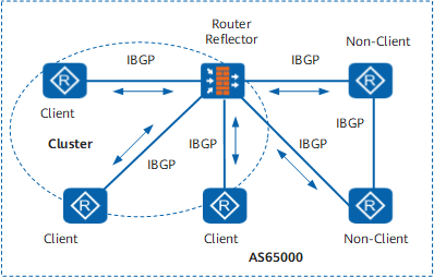
In an AS, one router severs as a Route Reflector (RR) and the other routers serve as clients. The clients establish IBGP connections with the RR. The RR and its clients form a cluster. The RR reflects routes between clients, and thus clients do not need to establish BGP connections.
A BGP router that functions neither an RR nor a client is called a non-client. A non-client must establish a fully meshed connection with an RR and with all the other non-clients, as shown in Figure 1.
Applications
After receiving routes from peers, an RR selects the optimal route based on BGP route selection policies. The RR advertises the learned routes to its IBGP peers according to the rules defined in RFC 2796.
- After learning routes from a non-client IBGP peer, the RR advertises the routes to all the clients.
- After learning routes from a client, the RR advertises the routes to all the other clients and all non-clients.
- After learning routes from an EBGP peer, the RR advertises the routes to all clients and non-clients.
An RR is easy to configure, because it needs to be configured only on the device that functions as a reflector, and clients do not need to know that they are clients.
On some networks, if clients of an RR establish fully meshed connections between each other, they can exchange routing information directly. In this case, route reflection between clients is unnecessary and occupies bandwidth. On the FW, the undo reflect between-clients command can be run to disable route reflection between clients, but routes between clients and non-clients can still be reflected. By default, route reflection between clients is enabled.
Originator_ID
The Originator_ID attribute and the Cluster_List attribute are defined in RFC 2796. They are used to detect and prevent routing loops.
The Originator_ID attribute is four bytes long and is generated by an RR. It carries the router ID of the originator of the route in a local AS.
- When a route is reflected by an RR for the first time, the RR adds the Originator_ID attribute to this route to identify the originating router of the route. If a route already has the Originator_ID attribute, the RR does not create a new Originator_ID.
- When another BGP speaker receives the route, it compares the Originator_ID added to the route with the local router ID. If the Originator_ID and the local router ID are the same, the BGP speaker ignores this route.
Cluster_List
To avoid routing loops between ASs, a BGP router uses the AS_Path attribute to record the ASs that a route passes through. The route with the local AS number is discarded by the router.
To avoid routing loops within an AS, a BGP router prohibits IBGP peers from advertising the routes learned from the local AS.
An RR is implemented on the basis that IBGP peers can advertise the routes learned from the local AS to each other. In this case, the Cluster_List attribute is introduced to avoid routing loops within an AS.
An RR and its clients form a cluster. In an AS, each RR is uniquely identified by a Cluster_ID.
To avoid routing loops, the RR uses the Cluster_List attribute to record the Cluster_IDs of all RRs that a route passes through.
The Cluster_List is composed of a series of Cluster_IDs. It records all the RRs that a route passes through. The Cluster_List is similar to the AS_Path list and is generated by an RR.
- When an RR reflects routes between its clients or between its clients and non-clients, the RR adds the local Cluster_ID to the top of the Cluster_List. If the Cluster_List is empty, the RR creates a new one.
- When receiving an updated route, the RR checks its Cluster_List. If the Cluster_List contains the local Cluster_ID, the RR discards the received route. If the Cluster_List does not contain the local Cluster_ID, the RR adds the local Cluster_ID to the Cluster_List, and then reflects the updated route.
Backup RR
To enhance the reliability of a network and avoid the single node fault, more than one RR needs to be configured in a cluster. RRs in the same cluster have the same Cluster_ID, thus avoiding routing loops. On the FW, you can run the reflector cluster-id command to configure the same Cluster_ID for all RRs in a cluster.
In the redundant environment, clients can receive multiple routes to the same destination from different RRs. Clients then apply route selection policies to select the optimal route.
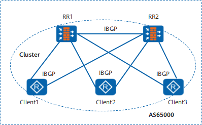
As shown in Figure 2, RR1 and RR2 are in the same cluster. RR1 and RR2 establish an IBGP connection. That is, the two RRs are non-clients.
- When Client 1 receives an updated route from an external peer, it advertises the route to RR1 and RR2 through IBGP.
- After receiving the updated route, RR1 reflects the route to other clients (Client 2 and Client 3) and non-clients (RR2) and adds the local Cluster_ID to the top of the Cluster_List.
- After receiving the reflected route, RR2 checks the Cluster_List. RR2 finds that its Cluster_ID is contained in the Cluster_List; therefore, it discards the updated route and does not reflect the route to its clients.

The application of the Cluster_List ensures that routing loops do not occur between RRs in the same AS.
Multiple Clusters in an AS
Multiple clusters may exist in an AS. RRs are IBGP peers of each other. An RR can be configured as a client or non-client of another RR. Therefore, the relationship between clusters in an AS can be configured flexibly.
For example, a backbone network is divided into multiple reflection clusters. Each RR is configured as a non-client of the other RRs, and these RRs are fully meshed. Each client establishes IBGP connections with only the RRs in the same cluster. In this manner, all BGP routers in the AS can receive the reflected routes.
Hierarchical Reflector
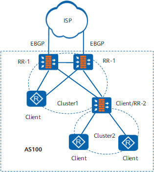
In the actual deployment of RRs, the scenario of the hierarchical reflector is usually used. As shown in Figure 3, the ISP provides Internet routes for AS 100. Two EBGP connections are established between the ISP and AS 100. AS 100 is divided into two clusters. The four routers in Cluster 1 are core routers.
- Two Level-1 RRs (RR-1) are deployed in Cluster 1. This redundant structure ensures the reliability of the core layer of AS 100. The other two routers at the core layer serve as clients of RR-1.
- One Level-2 RR (RR-2) is deployed in Cluster 2. RR-2 is the client of RR-1.