OSPF Areas
This section introduces OSPF areas and describes the feature of OSPF areas.
Before Area Partition
Suppose that all routers in a large-scale network run OSPF and the number of routers increases with the unceasing expansion of the network. The large number of routers results in a large LSDB on each router. Such an LSDB occupies a great amount of memory, complicates the operating of the SPF algorithm, and leads to the overload of routers.
With the expansion of networks, the possibility of topology changes is on the increase. That is, the network usually confronts "turbulence". A great number of OSPF packets are transmitted on the network, and the utilization of bandwidth is reduced. Each change in topology requires all the routers to recalculate the routes.
After Area Partition
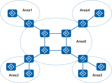
OSPF solves the preceding problem by dividing an AS into areas. An area is regarded as a logical router group. Each group is identified by an area ID. At the border of an area resides a router, rather than a link. A network segment (or a link) can belong to only one area. That is, each OSPF interface must belong to an area, as shown in Figure 1.
Backbone Area
After an OSPF network is divided into different areas, not all areas are equal. Among areas, one area with area ID as 0 is called the backbone area. The backbone area is responsible for forwarding the routes between areas. The routing information between the non-backbone areas must be forwarded through the backbone area.
OSPF defines two rules for a backbone area as below:
Connectivity must be available between non-backbone areas and the backbone area.
Connectivity must be available over the backbone area.
Virtual Link
In actual applications, the physical connectivity between the backbone area and non-backbone areas cannot be ensured due to various reasons. The problem can be solved by the configuration of an OSPF virtual link.
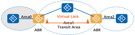
Virtual link refers to a logical channel established between two ABRs through a non-backbone area. The virtual link must be configured on both ends of a link. The transmit area refers to the area that provides an internal route of a non-backbone area for the two ends of a virtual link.
As shown in Figure 2, Area 2 is not directly connected to the backbone area. A virtual link is configured on ABRs to provide the connectivity between Area 2 and the backbone area.
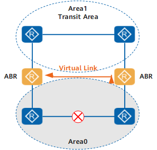
The virtual link also serves as a backup link. If a link fault occurs on the backbone area, the virtual link provides the logical connectivity for the backbone area, as shown in Figure 3.
The virtual link is similar to a point-to-point connection between two ABRs. Similar to physical interfaces, the interfaces on the virtual link can be configured with parameters such as the Hello interval.
When OSPF packets are transmitted between two ABRs, these packets are transparent for the intermediate routers enabled with OSPF. That is, the intermediate routers forward the packets as common IP packets without resolving them after detect that they are not the destinations of the packets.
Stub Area
A stub area is a special area where the ABRs do not flood the received routes outside the AS. In stub areas, the size of the routing tables of the routers and the routing information in transmission are reduced.
A stub area is an optional configuration. Not all areas can be configured as stub areas. Generally, a stub area is a non-backbone area with only one ABR and is located at the AS boundary.
To ensure the reachability to a destination outside the AS, the ABR in the stub area originates a default route and advertises it to the non-ABR routers in the stub area.
Note the following when configuring a stub area:
The backbone area cannot be configured as the stub area.
An ASBR cannot exist in a stub area. That is, external routes are not flooded in the stub area.
A virtual link cannot pass through a stub area.
NSSA
A new type of an area, Not-So-Stubby Area (NSSA), and a new type of an LSA, NSSA-LSA (or Type 7 LSA) are defined in RFC 1587.
As the NSSA is derived from the stub area, it resembles the stub area in many ways. Type 5 LSA is not allowed in the NSSA. The Type 7 LSA is generated by the ASBR in the NSSA, and is flooded only in the NSSA. When a Type 7 LSA reaches the ABR of the NSSA, the ABR translates the Type 7 LSA into an AS-External-LSA and floods it to the other areas. The ABR translating LSAs is also called the translator.
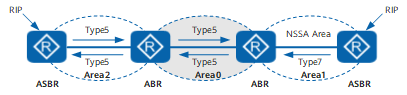
As shown in Figure 4, the AS that runs OSPF contains three areas, area 0, area 1, and area 2. The other two ASs run RIP. Area 1 is configured as the NSSA. After Area 1 transmits the received RIP routes to the ASBR in the NSSA, the ASBR originates Type 7 LSAs and floods them in Area 1. When Type 7 LSAs reach the ABR in the NSSA, the ABR translates them into Type 5 LSAs, and then floods them to Area 0 and Area 2.
On the other hand, the RIP routes in the AS that runs RIP in Area 2 are transmitted in the AS by Type 5 LSAs originated by ASBR in Area 2. Type 5 LSAs do not reach Area 1 because Area 1 is an NSSA.
Similar to the stub area, an NSSA cannot be configured with virtual links.
Features of Each Area
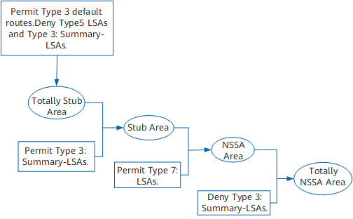
Figure 5 shows the differences between totally stub area, stub area, NSSA area, and totally NSSA area.
The features of the areas are as follows:
Totally stub area: allows the Type3 default routes advertised by ABR but not inter-area routes or those outside ASs.
Stub area: different from the totally stub area, the stub area allows inter-area routes.
NSSA area: different from the stub area, the NSSA area allows the import of external routes into the AS. The ASBR advertises Type 7 LSA to the NSSA area.
Totally NSSA area: different from the stub area, the NSSA area does not allow inter-area routes.