Configuring RIP Using the Web UI
This section describes how to use the Web UI to configure RIP.
Creating a RIP Process
- Choose .
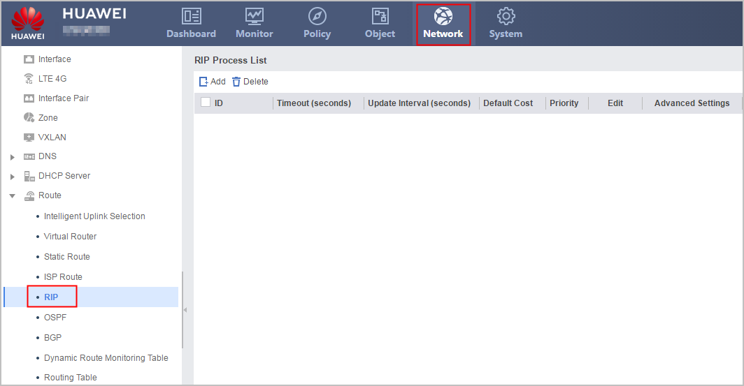
- Click Add.
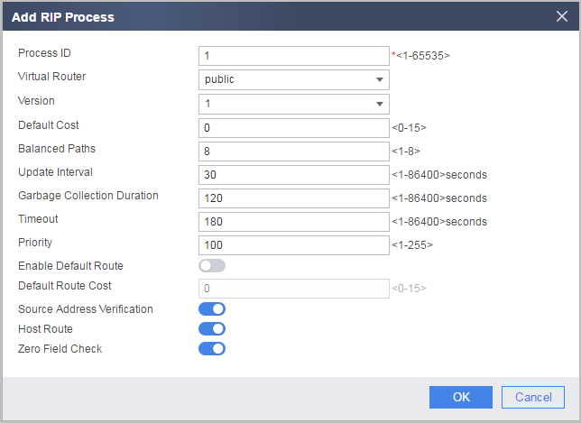
- Enter or select the parameters.
Parameter
Description
Process ID
The system supports RIP multi-process. If multiple RIP processes are enabled on one device, different process IDs need to be specified. An RIP process ID is a local concept. The devices with different process IDs can exchange packets in between.
Virtual Router
Indicates the virtual system. The VPN instance name indicates a common VPN or the VPN created for a virtual system.
When you configure an RIP route for a virtual system, the virtual router must be set to the VPN instance with the same name as the virtual system.
Version
Indicates the RIP version number.
Default Cost
Indicates the cost of running the RIP protocol.
Balanced Paths
Indicates the maximum number of equal-cost routes.
Update Interval
Indicates the interval of updating packets regularly in the RIP route.
Garbage Collection Time
Indicates the interval for collecting RIP garbage routes.
Timeout
Indicates the timeout interval of the RIP route.
Priority
Indicates the preference of the RIP.
Enable Default Route
Configures the default route for the situation that packets cannot find corresponding routing entries in the routing table.
Default Route Cost
Indicates the metric value of the default route.
This parameter is available when Enable Default Route is enabled.
Source Address Verification
Verifies the source IP address of a received RIP route update packet.
Zero Field Check
Checks the zero fields in a RIP-1 packet.
Certain fields in a RIP-1 packet must be zero. These fields are called zero fields.
If the interface version is set to RIP-1, zero field check is required on packets. This parameter is invalid for the RIP-2 packets because the zero field does not exist in RIP-2 packets.
Host Route
Indicates that host routes can be added to the routing table.
Route Aggregation
Enables the RIP-2 automatic route aggregation.
The RIP-1 sends routes with natural masks, that is, the routes are advertised in aggregation mode. The RIP-2 supports the subnet mask and Classless Inter-Domain Routing (CIDR).
If all subnet routes need to be broadcasted, you can disable the route aggregation function of the RIP-2 on the interface.
- Click OK.
If the new RIP process is displayed on the page, the operation succeeds.
Configuring a Network Segment for a RIP Process
- Choose .
- Click
 corresponding to the RIP process to be modified.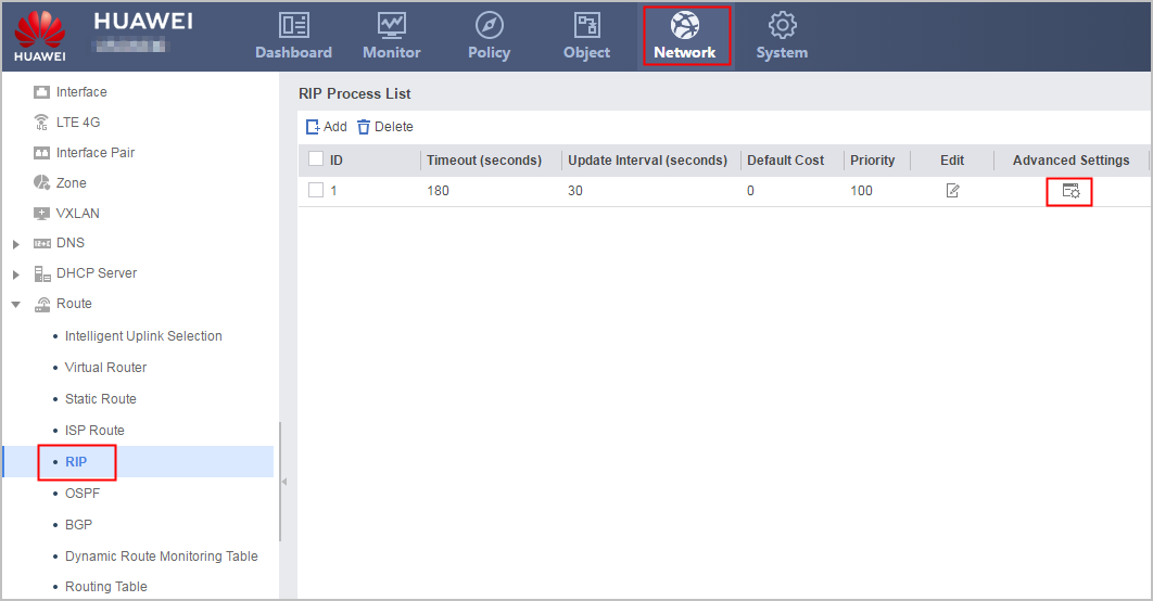
- In the RIP Process ID:ID navigation tree, choose .
- Click Add.
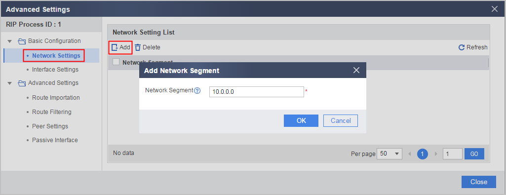
- Enter a network segment address to be added.

RIP supports the following natural network segments:
1 to 126.0.0.0, 128 to 191.x.0.0, 192 to 223.x.x.0.
- Click Confirm.
If the new network segment is displayed on the page, the operation succeeds.
Modifying a RIP Interface
- Choose .
- Click corresponding to the RIP process to be modified.
- In the RIP Process ID:ID navigation tree, choose .
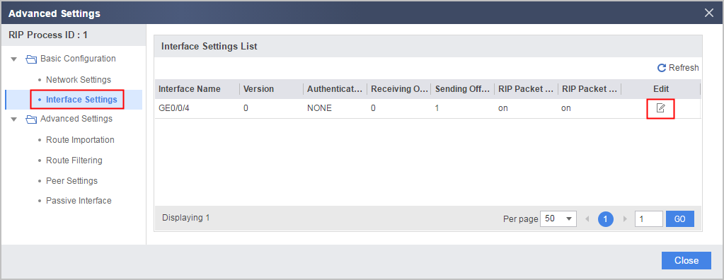
- Click
 corresponding to the interface to be configured.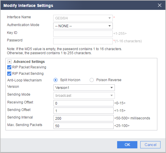
- Enter or select the parameters.
Parameter
Description
Interface Name
Indicate the name of a RIP interface.
Authentication Mode
Indicates the mode in which the interface authenticates packets.
- NONE: indicates that authentication is not performed on packets.
- Simple: indicates that simple authentication is performed on packets.
- MD5: indicates that MD5 authentication is performed on packets.
- HMAC-SHA256: indicates that HMAC-SHA256 authentication is performed on packets.
MD5 Key
Indicates the identifier of the MD5 authentication key.
This parameter is required when Authentication Mode is the MD5 authentication.
Password
Indicates the authentication key.
This parameter is required when Authentication Mode is the MD5 authentication or simple authentication.
Confirm Password
Confirms the password.
This parameter is required when Authentication Mode is the MD5 authentication.
Advanced Settings
RIP Packet Receiving
Indicates that the interface is allowed to receive RIP update packets.
RIP Packet Sending
Indicates that the interface is allowed to send RIP update packets.
Anti-Loop Mechanism
Split Horizon: indicates that the interface does not send the routes received by the interface.
Poison Reverse: RIP learns the route of the packet from an interface, sets the route cost to 16 (unreachable), and sends the packet to the neighbor router through the original interface.
Version
Indicates the version of RIP packets received by the interface.
The RIP has two versions: RIP-1 and RIP-2. The RIP-1 is a classful routing protocol, supporting the advertisement of protocol packets in broadcast mode. The RIP-2 is a classless routing protocol, supporting the transmission of packets in both broadcast mode and multicast mode.
Sending Mode
The RIP-2 packets can be transferred in two modes: broadcast and multicast.
Receiving Offset
Indicates the metric value added when the interface receives routes.
Sending Offset
Indicates the metric value added when the interface sends routes.
Sending Interval
Indicates the interval for the interface to send update packets.
Max. Sending Packets
Indicates the number of update packets allowed on the interface each time.
- Click Confirm.
Configuring Route Importing for a RIP Process
If a router runs the RIP and other routing protocols, you can configure the RIP to import external route information, and to filter out unnecessary routes and specify a metric value. If no metric value is specified, the default metric value takes effect.
- Choose .
- Click corresponding to the RIP process to be modified.
- In the RIP Process ID:ID navigation tree, choose .
- Click Add.
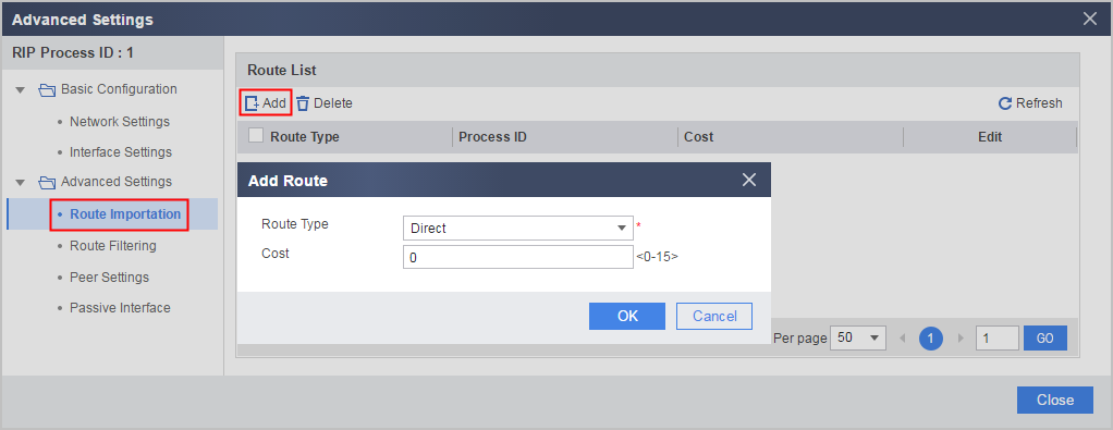
- Enter or select the parameters.
Table 1 Adding a route import configuration Parameter
Description
Route Type
Indicates the imported source routing protocol.
Process ID
The routing protocol process ID needs to be specified when the route type is ospf, rip, or isis.
Cost
Indicates the cost of an imported route.
- Click Confirm.
If the new route import configuration is displayed on the page, the operation succeeds.
Configuring Route Filtering
A router provides a routing information filtering function. By specifying an ACL and an IP address prefix list, you can configure an ingress or egress filtering policy to filter the received and released routes.
- Choose .
- Click corresponding to the RIP progress to be modified.
- In the RIP Process ID:ID navigation tree, choose .
- Click Add.
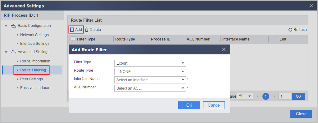
- Enter or select the parameters.
Parameter
Description
Filter Type
Indicate the route filter type of the RIP. After this parameter is set, it cannot be changed.
Import: indicates that the RIP filters received routing information.
Export: indicates that the RIP filters advertised routing information.
Route Type
Advertise routes by the route type based filtering. This parameter is required when the filter type is export. After this parameter is set, it cannot be changed.
Process ID
Specifies the process ID for OSPF, RIP, and ISIS. After this parameter is set, it cannot be changed.
Interface Name
Advertises routes by the egress based filtering. After this parameter is set, it cannot be changed.
Either route type based filtering or egress based filtering can be selected.
ACL Number
Sets a matching rule based on the ACL. It is used for filtering routes according to destination IP addresses.
Indicates the basic ACL number.
You can select an existed ACL or select Basic ACL to create a new ACL.
Source Address, Schedule, and Action are available when ACL is Basic ACL.
NOTE:When deleting route filtering configurations, you can delete the referenced ACL or delete only route filtering configurations.
Source Address
Indicates the source IP address for filtering routes or the name of the source address/address group.
You can select an existed address/address group or create a new address/address group.
Schedule
Indicates the time range during which route filtering takes effect.
You can select an existed time range or create a new time range.
Action
Indicates the action taken by the device towards the route.
- permit: indicates the action configured by the policy is performed on the route.
- deny: indicates that the action configured by the policy is not performed on the route.
- Click OK.
If the new route filtering policy is displayed on the page, the operation succeeds.
Configuring a RIP Peer
Usually, the RIP sends packets by using broadcast or multicast addresses.
To use the RIP as a routing protocol on a network that does not support broadcasting or multicasting, you need to specify a RIP peer manually.
- Choose .
- Click corresponding to the RIP progress to be modified.
- In the RIP Process ID:ID navigation tree, choose .
- Click Add.
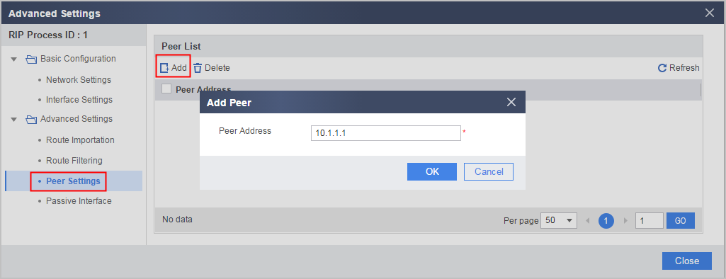
- Enter the IP address of the RIP peer.
- Click Confirm.
If the new RIP peer is displayed on the page, the operation succeeds.
Configuring a Passive Interface
After an interface is configured not to send RIP update packets, the interface does not send RIP updates to networks. This does not affect the advertisement of directly connected routes. This function enhances the RIP networking capability and reduces the system resource consumption.
- Choose .
- Click corresponding to the RIP progress to be modified.
- In the RIP Process ID:ID navigation tree, choose .
- Click Add.
- Select the interface to be disabled.
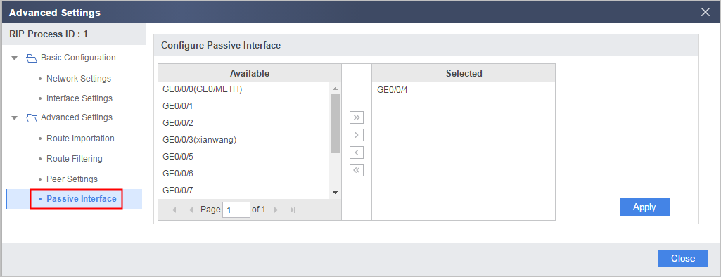
- Click Confirm.
If the new passive interface is displayed on the page, the operation succeeds.