Applications of Static Routes
As shown in Figure 1, the network topology is simple, and network communication can be implemented through static routes. It is required to specify an address for each physical network, identify indirectly-connected physical networks for each router, and configure static routes for the indirectly-connected physical networks.
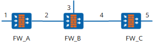
In Figure 1, static routes to networks 3, 4, and 5 need to be configured on FW_A; static routes to networks 1 and 5 need to be configured on FW_B; static routes to networks 1, 2, and 3 need to be configured on FW_C.
Default Static Route
When the ip route-static command is run to configure a static route, if the destination address and the mask are set to all 0s (0.0.0.0 0.0.0.0), it indicates that a default route is configured. This simplifies the network configuration.
In Figure 1, because the next hop of the packets sent by FW_A to networks 3, 4, and 5 is FW_B, a default route can be configured on FW_A to replace the three static routes destined for networks 3, 4, and 5 in the preceding example. Similarly, only a default route from FW_C to FW_B needs to be configured to replace the three static routes destined for networks 1, 2, and 3 in the preceding example.
Floating Static Routes
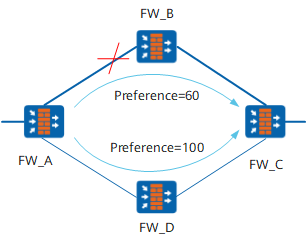
Different static routes can be configured with different preferences so that routing management policies can be flexibly applied. Specifying different preferences for multiple routes to the same destination can implement route backup.
As shown in Figure 2, there are two static routes from FW_A to FW_C. Normally, in the routing table, only the static route with the next hop being FW_B is in the Active state because this route has a higher preference. The other static route with the next hop being FW_D functions as a backup route. The backup route is activated to forward data only when the primary link becomes faulty. After the primary link recovers, the static route with the next hop being FW_B becomes active to forward data. Therefore, the backup route is also called a floating static route. The floating static route becomes ineffective when a fault occurs on the link between FW_B and FW_C.
Load Balancing Among Static Routes
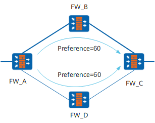
Specifying the same preference for multiple routes to the same destination can implement load balancing.
As shown in Figure 3, there are two static routes with the same preference from FW_A to FW_C. The two routes exist in the routing table and forward data at the same time.