Web: Example for Configuring Virtual Systems to Isolate Enterprise Departments (Layer-3 Access, Virtual Systems Having Independent WAN Interfaces)
The FW functions as the access gateway of the office area of a large campus network to protect the intranet. The intranet has multiple service departments, and the administrator configures virtual systems for each department to implement independent management over department networks.
Networking Requirements
As shown in Figure 1, a FW is deployed in area of the large campus network as the gateway. The network of area A comprises the R&D and non-R&D departments, and the two departments have different network access permissions. Requirements are as follows:
- Some employees in the R&D department can access the Internet, and all employees in the non-R&D department can access the Internet.
- The R&D and non-R&D departments are isolated from each other and cannot communicate.
- The service volumes of the R&D and non-R&D departments are nearly the same. Therefore, the same virtual system resources are allocated to them.
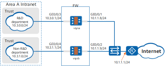
Data Planning
Item |
Data |
Description |
|---|---|---|
vsysa |
|
- |
vsysb |
|
- |
Resource class |
|
- |
Configuration Roadmap
- The public system administrator creates two virtual systems vsysa, and vsysb, assigns resources.
- The public system administrator configures IP addresses, routes, security policies, and NAT policies for vsysa.
- The public system administrator configures IP addresses, routes, security policies, and NAT policies for vsysb.
Procedure
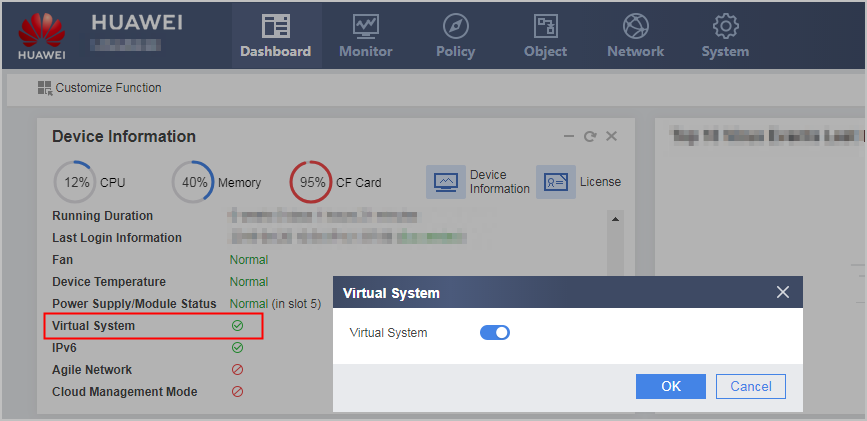
- Click Dashboard on the main menu. In the Device Information area, click Configure on the line of Virtual System to enable the virtual system function.
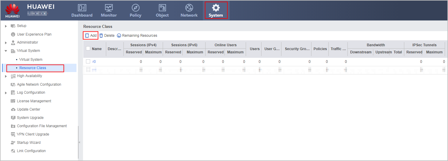
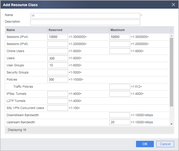
- Configure a resource class.
- In the root system, create virtual systems vsysa and vsysb and allocate resources to them.
- Choose .
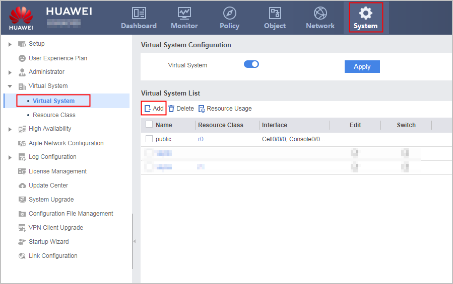
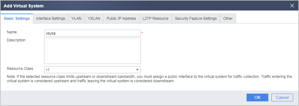
- Click Add and then the Basic Settings tab and set the following parameters.
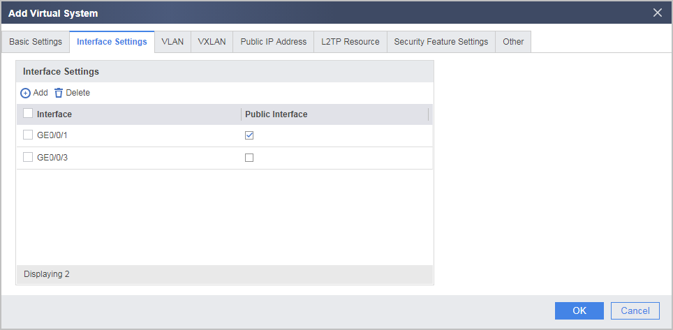
- Click the Interface Settings tab and allocate interfaces to the virtual system.
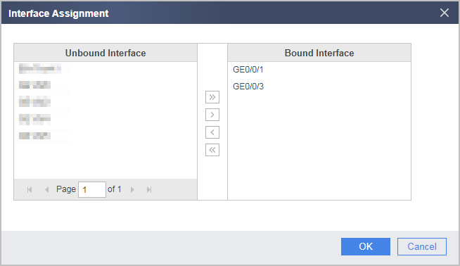
- Set GE0/0/1 as the public interface.

Bandwidth resource configurations in resource classes take effect only after the public interface is configured.
In this example, the bandwidth should be limited for intranet users to access the Internet. Set WAN interface GE0/0/1 as the public interface. Then all traffic from intranet users to the Internet is forwarded through GE0/0/1, which is called the outgoing direction. This function can work with Uplink Bandwidth configured in 2.b to limit the bandwidth for intranet users to access the Internet.
- Choose .
- Set IP addresses in vsysa.
- Select vsysa from the Virtual System drop-down list in the upper right corner to access vsysa.
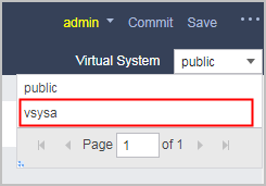
- Select vsysa from the Virtual System drop-down list in the upper right corner to access vsysa.
- Configure routes in vsysa.
- Choose .
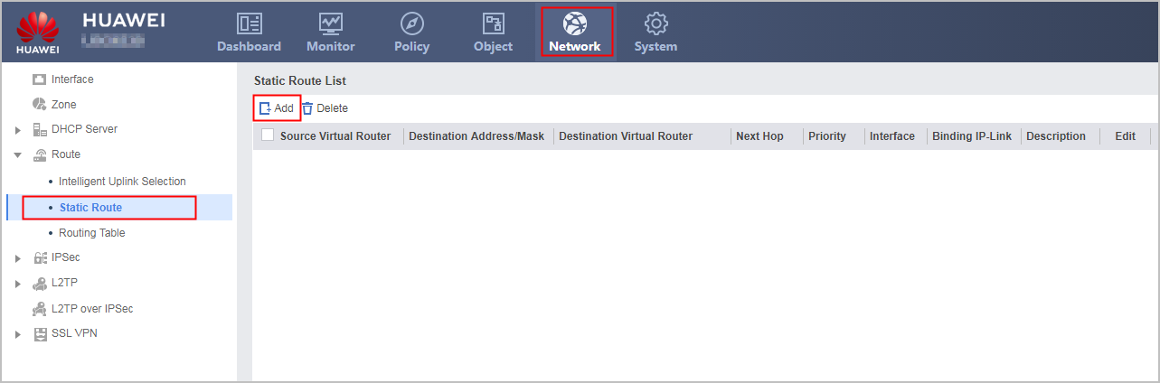
- Choose .
- Configure security policies in vsysa.
- Choose .
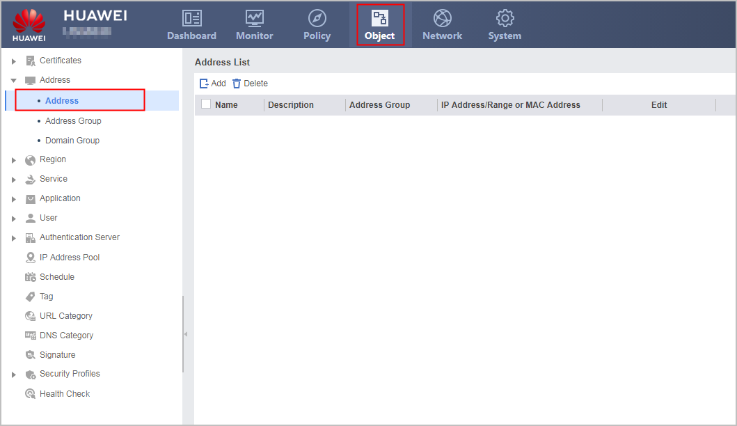
- Choose .
- Configure a NAT policy in vsysa.
- The public system administrator configures IP addresses, routes, security policies, and NAT policies for vsysb.
The configuration is similar to that of the R&D department except the following:
- The IP address of the inside interface is different.
- You do not need to create an IP address range for the non-R&D department. You only need to configure a security policy to allow all IP addresses to access the Internet.
- The outbound interface of the NAT policy must be set to GE0/0/2, and the source address must be set to any.
Verification
- Use a PC that is allowed to access the Internet and a PC that is not allowed to access the Internet from the R&D department and use the PCs to access the Internet. If the results are as expected, the IP addresses, security policies and NAT policies of vsysa are correctly configured.
- Access the Internet from the non-R&D department. If the access succeeds, the IP addresses, security policies and NAT policies of vsysb are correctly configured.
Configuration Scripts
Configuration script of the public system
#
 sysname FW
#
 vsys enable
#
resource-class r1
 resource-item-limit session reserved-number 10000 maximum 50000
 resource-item-limit policy reserved-number 300
 resource-item-limit user reserved-number 300
 resource-item-limit user-group reserved-number 10
 resource-item-limit bandwidth 20 outbound
#
vsys name vsysa 1
 assign resource-class r1
 assign interface GigabitEthernet0/0/1
 assign interface GigabitEthernet0/0/3
#
vsys name vsysb 2
 assign resource-class r1
 assign interface GigabitEthernet0/0/2
 assign interface GigabitEthernet0/0/4
#
interface GigabitEthernet0/0/1
 set public-interface
#
interface GigabitEthernet0/0/2
 set public-interface
#
return
Configuration script of vsysa
#
interface GigabitEthernet0/0/1
 ip address 10.1.1.8 255.255.255.0
#
interface GigabitEthernet0/0/3
 ip address 10.3.0.1 255.255.255.0
#
firewall zone trust
 set priority 85
 add interface GigabitEthernet0/0/3
#
firewall zone untrust
 set priority 5
 add interface GigabitEthernet0/0/1
#
ip address-set ipaddress1 type object
 address 0 range 10.3.0.2 10.3.0.10
#
 ip route-static 0.0.0.0 0.0.0.0 10.1.1.1
#
security-policy
 rule name to_internet
  source-zone trust
  destination-zone untrust
  source-address address-set ipaddress1
  action permit
#
 nat-policy
  rule name nat1
   source-zone trust
   egress-interface GigabitEthernet0/0/1
   source-address address-set ipaddress1
   action source-nat easy-ip
#
return
Configuration script of vsysb
#
interface GigabitEthernet0/0/2
 ip address 10.1.1.9 255.255.255.0
#
interface GigabitEthernet0/0/4
 ip address 10.3.1.1 255.255.255.0
#
firewall zone trust
 set priority 85
 add interface GigabitEthernet0/0/4
#
firewall zone untrust
 set priority 5
 add interface GigabitEthernet0/0/2
#
 ip route-static 0.0.0.0 0.0.0.0 10.1.1.1
#
security-policy
 rule name to_internet
  source-zone trust
  destination-zone untrust
  action permit
#
 nat-policy
  rule name nat1
   source-zone trust
   egress-interface GigabitEthernet0/0/2
   action source-nat easy-ip
#
return