Web: Example for Configuring Virtual Systems on a Cloud Computing Gateway
This section provides an example for configuring virtual systems to protect a cloud computing data center.
Networking Requirements
Figure 1 shows the networking diagram, a cloud computing data center uses a FW for security protection of the egress gateway to meet the following requirements:
- Customers of the data center can independently manage and access their server resources.
- The FW has only one outside interface but provides sufficient public IP addresses. NAT policies are configured on the FW so that customers have independent public IP addresses to access their own server resources.
- As enterprises A and B have different amount of service traffic, they purchase separate virtual system resources.
Configure virtual systems to meet the preceding requirements.
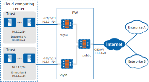
Data Planning
Item |
Data |
Description |
|---|---|---|
public |
|
In this example, all intranet servers provide services to Internet users through the public system's outside interface. |
vsysa |
|
In this example, IP address mapping must be configured so that the server at the private address 10.3.0.2 can use the public address 1.1.1.2 to provide services to users of enterprise A. The public system administrator configures and manages virtual systems, and no virtual system administrator is required. |
vsysb |
|
In this example, IP address mapping must be configured so that the server at the private address 10.3.1.2 can use the public address 1.1.1.3 to provide services to users of enterprise B. The public system administrator configures and manages virtual systems, and no virtual system administrator is required. |
Resource class |
|
In this example, create two resource classes and bind each to a virtual system. |
Configuration Roadmap
- The public system administrator creates virtual systems vsysa and vsysb and allocates resources to them.
- Create subinterfaces GE0/0/2.1 and GE0/0/2.2 on the GE0/0/2 and configure these two subinterfaces as inside interfaces of vsysa and vsysb, respectively.
- The public system administrator configures IP address mapping for vsysa and vsysb.
- The public system administrator configures routes and security policies for vsysa and vsysb.
Procedure
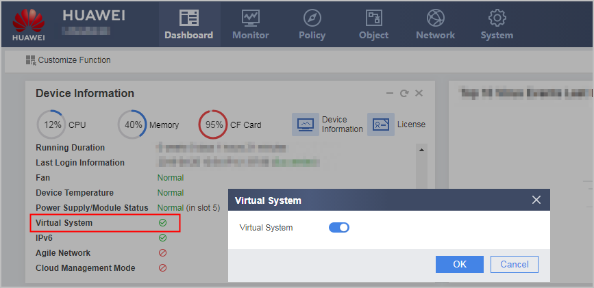
- Click Dashboard on the main menu. In the Device Information area, click Configure on the line of Virtual System to enable the virtual system function.
- Configure a resource class.
- Choose .
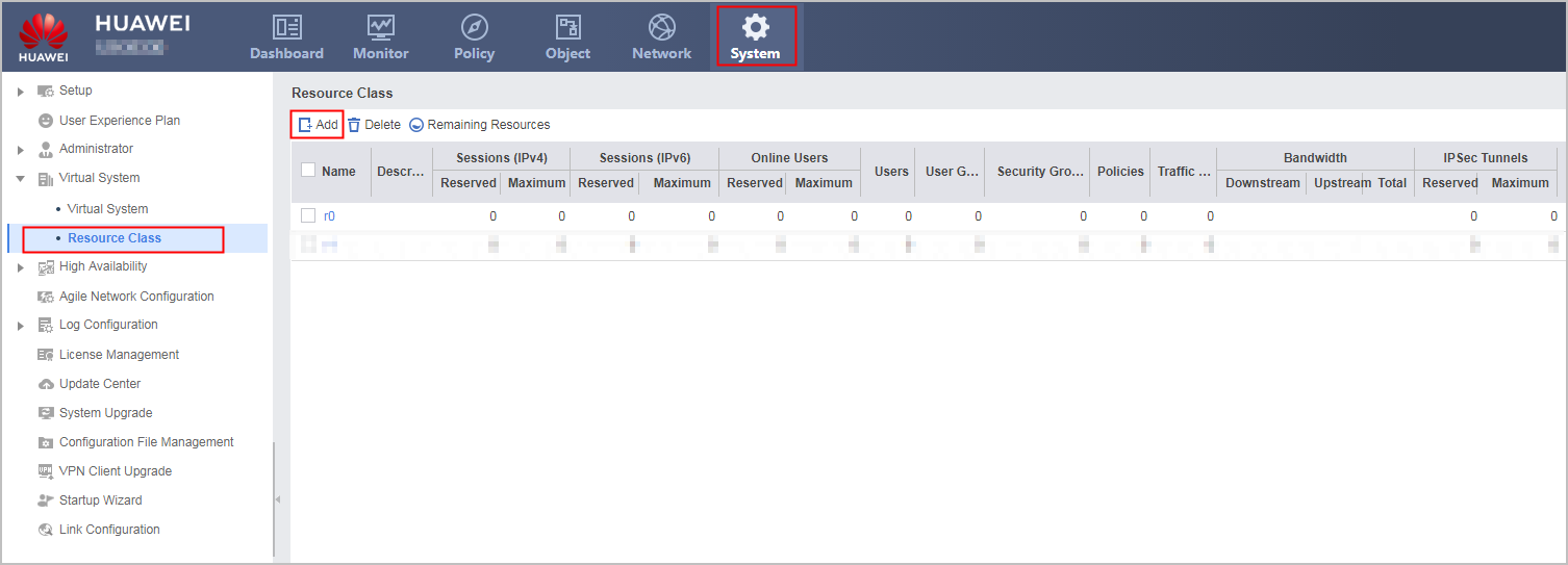
- Click Add and set the following parameters.
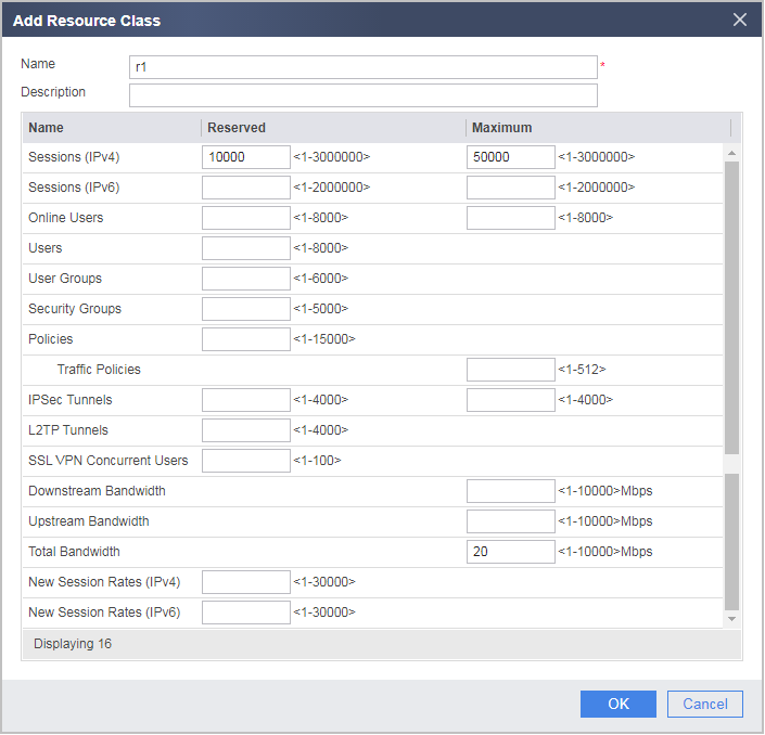
- Create resource class r2 according to the preceding steps.
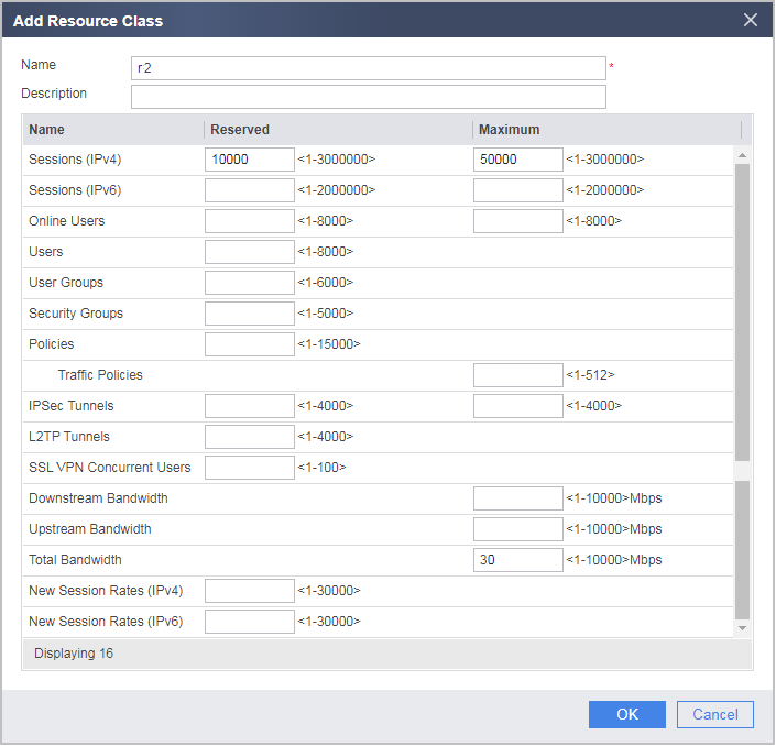
- Choose .
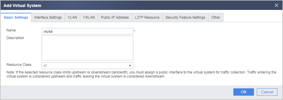
- In the root system, create virtual systems vsysa and vsysb and allocate resources to them.
- Choose .
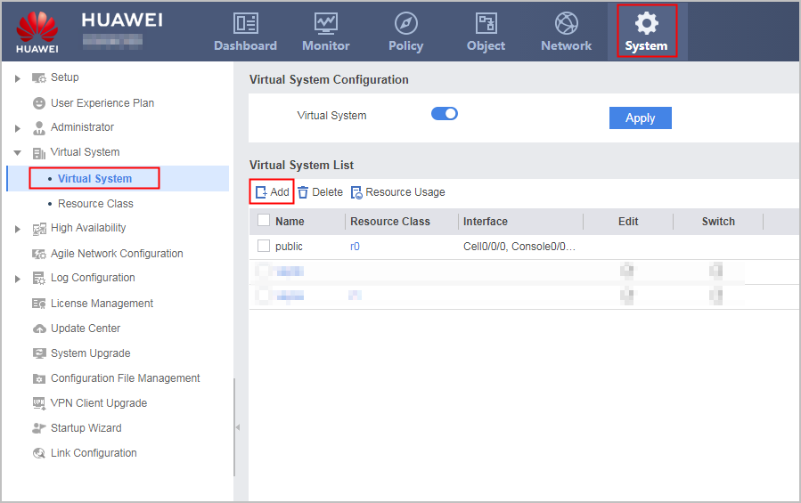
- Click Add and then the Basic Settings tab and set the following parameters.
- Choose .
- Create GigabitEthernet 0/0/2.1 and GigabitEthernet 0/0/2.2.
- Click Add to create GigabitEthernet 0/0/2.1 based on the following parameter values.
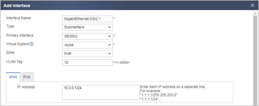
- Repeat these steps to create GigabitEthernet 0/0/2.2 based on the following parameter values.
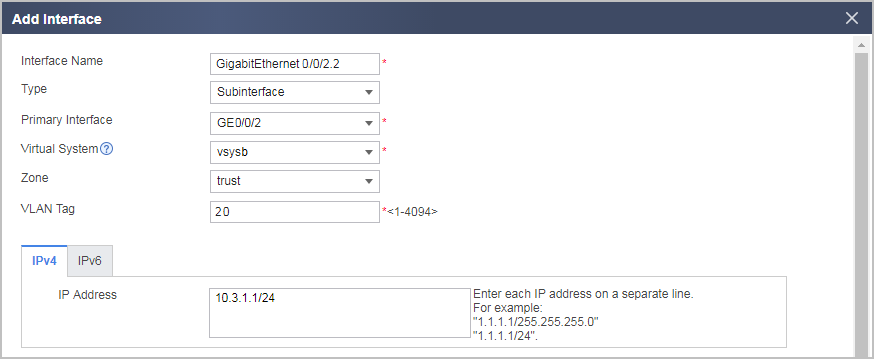
- Click Add to create GigabitEthernet 0/0/2.1 based on the following parameter values.
- In the root system, configure the WAN and virtual interfaces.
- Click the interface name and set the following parameters for the interface.

The IP address of a Virtual-if interface can be set to any address different from the IP addresses of all the other interfaces.
The IDs of Virtual-if interfaces are randomly assigned from available IDs in the system. Therefore, the virtual interfaces may not be Virtual-if 1 or Virtual-if 2 in practice.
Interface
GigabitEthernet 0/0/1
Virtual-if 0
Virtual-if 1
Virtual-if 2
Security Zone
untrust
trust
untrust
untrust
IP Address
1.1.1.1/24
172.16.0.1/24
172.16.1.1/24
172.16.2.1/24
- Click the interface name and set the following parameters for the interface.
- Configure routes in the root system.
- Choose .
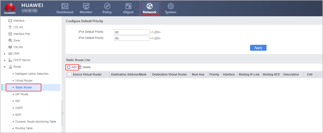
- Choose .
- Configure a security policy in the root system.
- Configure a NAT policy in the root system.
- Choose .
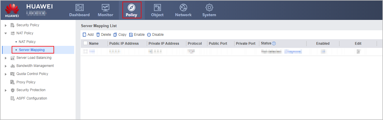
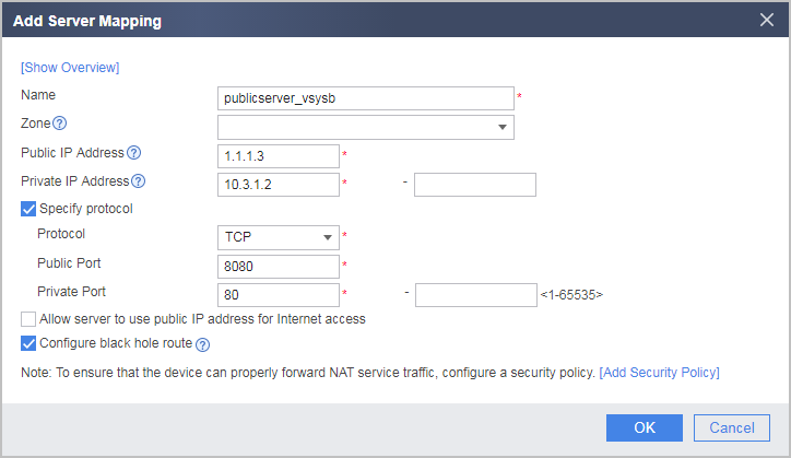
- Click Add and configure a server mapping for vsysa based on the following parameter values.
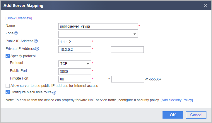
- Repeat these steps to configure a server mapping for vsysb based on the following parameter values.
- Choose .
- Configure routes in vsysa.
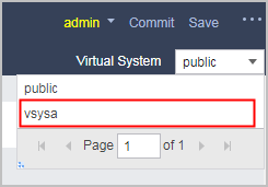
- Select vsysa from the Virtual System drop-down list in the upper right corner to access vsysa.
- Choose .
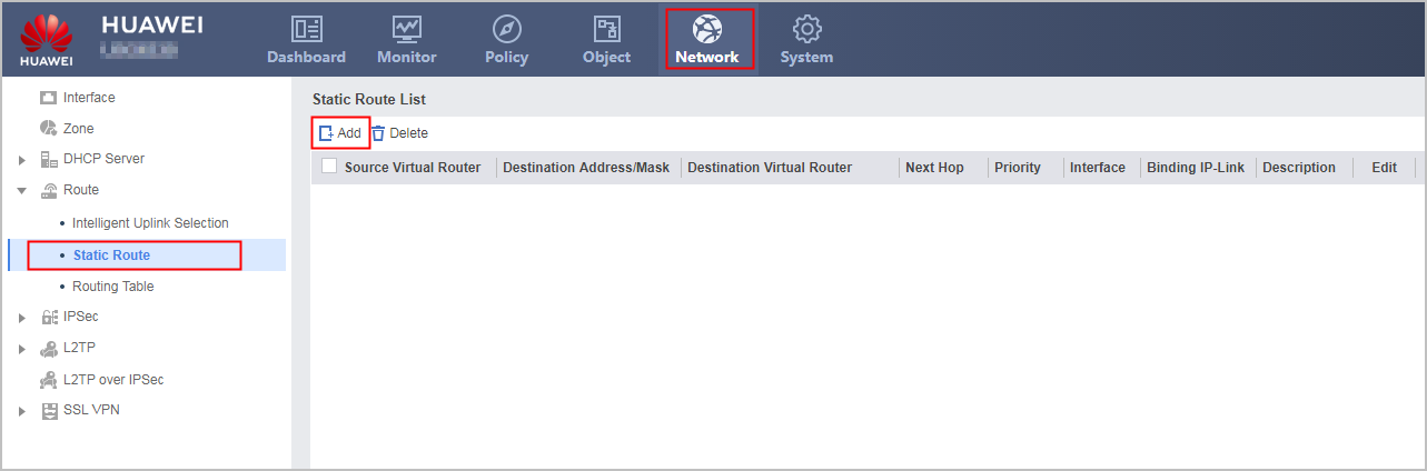
- Select vsysa from the Virtual System drop-down list in the upper right corner to access vsysa.
- Configure the following security policy in vsysa to allow enterprise users to access intranet servers.
- Configure routes and security policies on vsysb.
The details are omitted because the configurations are the same as those of vsysa, except the IP addresses.
Verification
- Access http://1.1.1.2:8080 from enterprise A. If the access succeeds, IP address mapping and security policies are correctly configured.
- Access http://1.1.1.3:8080 from enterprise B. If the access succeeds, IP address mapping and security policies are correctly configured.
Configuration Scripts
Configuration script of the public system
#
 sysname FW
#
 vsys enable
#
 nat server publicserver_vsysa 0 protocol tcp global 1.1.1.2 8080 inside 10.3.0.2 www no-reverse
 nat server publicserver_vsysb 1 protocol tcp global 1.1.1.3 8080 inside 10.3.1.2 www no-reverse
#
resource-class r1
 resource-item-limit session reserved-number 10000 maximum 50000
 resource-item-limit bandwidth 20 entire
#
resource-class r2
 resource-item-limit session reserved-number 10000 maximum 50000
 resource-item-limit bandwidth 30 entire
#
vsys name vsysa 1
 assign resource-class r1
 assign interface GigabitEthernet0/0/2.1
#
vsys name vsysb 2
 assign resource-class r2
 assign interface GigabitEthernet0/0/2.2
#
interface GigabitEthernet0/0/1
 ip address 1.1.1.1 255.255.255.0
#
interface GigabitEthernet0/0/2.1
 vlan-type dot1q 10
 ip binding vpn-instance vsysa
#
interface GigabitEthernet0/0/2.2
 vlan-type dot1q 20
 ip binding vpn-instance vsysb
#
interface Virtual-if0
 ip address 172.16.0.1 255.255.255.0
#
firewall zone trust
 set priority 85
 add interface Virtual-if0
#
firewall zone untrust
 set priority 5
 add interface GigabitEthernet0/0/1
#
 ip route-static 0.0.0.0 0.0.0.0 1.1.1.254
 ip route-static 10.3.0.0 255.255.255.0 vpn-instance vsysa
 ip route-static 10.3.1.0 255.255.255.0 vpn-instance vsysb
#
security-policy
 rule name internet_to_server
  source-zone untrust
  destination-zone trust
  destination-address 10.3.0.0 16
  action permit
#
return
Configuration script of vsysa
#
interface GigabitEthernet0/0/2.1
 vlan-type dot1q 10
 ip address 10.3.0.1 255.255.255.0
 ip binding vpn-instance vsysa
#
interface Virtual-if1
 ip address 172.16.1.1 255.255.255.0
#
firewall zone trust
 set priority 85
 add interface GigabitEthernet0/0/2.1
#
firewall zone untrust
 set priority 5
 add interface Virtual-if1
#
 ip route-static 0.0.0.0 0.0.0.0 public
#
security-policy
 rule name internet_to_server
  source-zone untrust
  destination-zone trust
  destination-address 10.3.0.0 24
  action permit
#
return
Configuration script of vsysb
#
interface GigabitEthernet0/0/2.2
 vlan-type dot1q 20
 ip address 10.3.1.1 255.255.255.0
 ip binding vpn-instance vsysb
#
interface Virtual-if2
 ip address 172.16.2.1 255.255.255.0
#
firewall zone trust
 set priority 85
 add interface GigabitEthernet0/0/2.2
#
firewall zone untrust
 set priority 5
 add interface Virtual-if2
#
 ip route-static 0.0.0.0 0.0.0.0 public
#
security-policy
 rule name internet_to_server
  source-zone untrust
  destination-zone trust
  destination-address 10.3.1.0 24
  action permit
#
return