FAQ About Virtual System
This section describes frequently asked questions (FAQs) about virtual system.
How Can I Use VPN Instances to Isolate Sessions When Packets Pass Through the FW Twice?
As shown in Figure 1, the gateway address of the PC is set to the IP address (192.168.0.1) of VLANIF10 on the Layer-3 switch. The PC logs in to the FW with the Layer-3 switch as the relay for management.
At the first time, the packets from the PC to the FW traverse the FW through VLANIF10. At the second time, the packets are forwarded to the FW from VLANIF20. The packets pass through the FW twice, but the FW cannot distinct the two sessions, causing the PC login failure.
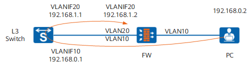
In such cases, you can configure a VPN instance to isolate the sessions.
<sysname> system-view
[sysname] ip vpn-instance vpn1
[sysname-vpn-instance-vpn1] ipv4-family
[sysname-vpn-instance-vpn1-af-ipv4] route-distinguisher 1:1
[sysname-vpn-instance-vpn1-af-ipv4] vpn-target 2:1
[sysname-vpn-instance-vpn1-af-ipv4] quit
[sysname-vpn-instance-vpn1] quit
Then bind the VPN instance to VLANIF20.
[sysname] interface Vlanif 20
[sysname-Vlanif20] ip binding vpn-instance vpn1
[sysname-Vlanif20] quit
Configure a route to the specified VPN instance and set the next hop to the IP address (192.168.1.1) of VLANIF20 on the Layer-3 switch.
[sysname] ip route-static vpn-instance vpn1 192.168.0.0 24 192.168.1.1
Configure security policies to allow traffic to pass through or access FW. Assume that the interface connecting FW to the Layer-3 switch is added to the trust zone, the interface connecting FW to the PC is added to the untrust zone, and VLANIF 20 is added to the dmz zone.
[sysname] security-policy
[sysname-policy-security] rule name pc_to_sw
[sysname-policy-security-rule-pc_to_sw] source-zone untrust
[sysname-policy-security-rule-pc_to_sw] destination-zone trust
[sysname-policy-security-rule-pc_to_sw] source-address 192.168.0.2 24
[sysname-policy-security-rule-pc_to_sw] destination-address 192.168.1.2 24
[sysname-policy-security-rule-pc_to_sw] action permit
[sysname-policy-security-rule-pc_to_sw] quit
[sysname-policy-security] rule name sw_to_local
[sysname-policy-security-rule-sw_to_local] source-zone dmz
[sysname-policy-security-rule-sw_to_local] destination-zone local
[sysname-policy-security-rule-sw_to_local] source-address 192.168.0.2 24
[sysname-policy-security-rule-sw_to_local] destination-address 192.168.1.2 24
[sysname-policy-security-rule-sw_to_local] action permit
[sysname-policy-security-rule-sw_to_local] quit
[sysname-policy-security] quit
After you configure a VPN instance to isolate the sessions, the PC can log in to the FW.
You may also encounter another scenario. As shown in Figure 2, the gateway address of the PC is set to the IP address (192.168.0.1) of VLANIF10 on the Layer-3 switch. The PC logs in to the FW with the Layer-3 switch as the relay.
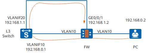
Similar with scenario 1, you need to bind a VPN instance on GE0/0/1 to isolate sessions.
How Can I Configure Virtual Systems to Isolate Services of Different VLANs When the FW Is Transparently Connected?
As shown in Figure 3, VLAN10 and VLAN20 have overlapping IP addresses. Before the FW is transparently connected, VLANs are used to isolate services. After the FW is transparently connected, there may be two traffic flows with the same source IP address, source port, destination IP address, and destination port. If so, the FW fails to distinct the sessions, affecting normal services.
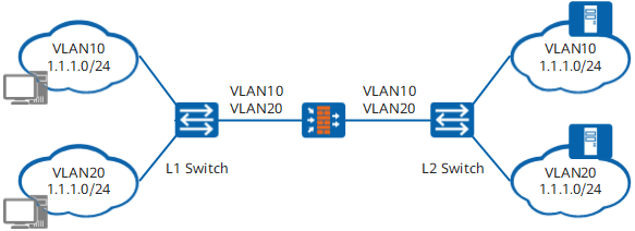
In such cases, you can configure two virtual systems (or configure one public system and one virtual system) on the FW and allocate VLAN10 and VLAN20 to different virtual systems. In this way, the traffic of the two VLANs is separated.
How Can I Allocate Vlanif Interfaces to Virtual Systems?
When a VLAN is allocated to a virtual system, the Vlanif interfaces in the VLAN are automatically allocated to the virtual system. Vlanif interfaces can be created only in the root system.
To allocate Vlanif 10 to the virtual system vsysa, do as follows:
<FW> system-view
[FW] vlan batch 10
[FW] interface vlanif 10
[FW-Vlanif10] quit
[FW] vsys name vsysa
[FW-vsys-vsysa] assign vlan 10
[FW-vsys-vsysa] quit
[FW] interface vlanif 10
[FW-Vlanif10] display this
#
interface Vlanif10
 ip binding vpn-instance vsysa
Do Virtual Systems Support Dynamic Routes?
Dynamic routes can not be configured in the virtual system. You need to configure and bind a VPN instance with the same name as the virtual system in the root system.
For example, bind the OSPF process to the VPN instance with the same name as the virtual system.
[FW] ospf 10 router-id 10.2.0.1 vpn-instance vsysa
[FW-ospf-10] area 0
[FW-ospf-10-area-0.0.0.0] network 10.2.0.0 0.0.0.255
[FW-ospf-10-area-0.0.0.0] quit
[FW-ospf-10] quit
For example, bind the BGP IPv4 address family to the VPN instance with the same name as the virtual system.
[FW] ip vpn-instance vsysa
[FW-vpn-instance-vsysa] ipv4-family
[FW-vpn-instance-vsysa-af-ipv4] route-distinguisher 100:1
[FW-vpn-instance-vsysa-af-ipv4] quit
[FW-vpn-instance-vsysa] quit
[FW] bgp 65009
[FW-bgp] ipv4-family vpn-instance vsysa
[FW-bgp-vsysa] router-id 10.3.0.1
[FW-bgp-vsysa] peer 10.3.0.2 as-number 65009
[FW-bgp-vsysa] quit
[FW-bgp] quit