Communication Between Two Virtual Systems Across a Shared Virtual System (Shared-vsys)
In addition to direct communication between two virtual systems, the FW also supports indirect communication between two virtual systems across a shared virtual system (Shared-vsys). That is, a shared virtual system is deployed between the two virtual systems for routing purposes.
Before configuring communication between two virtual systems across a shared virtual system, run the firewall forward cross-vsys extended command in the system view of the root system to configure the communication mode of the virtual systems to the extended mode.
In extended mode, the device introduces the concept of shared virtual system (Shared-vsys). A shared virtual system in extended mode is created on the FW for routing, which helps implement communication between two virtual systems across Shared-vsys. As shown in Figure 1, packets between vsysa and vsysb are forwarded across Shared-vsys. The FW mode is set to extended mode, and therefore packets from vsysa are forwarded across Shared-vsys to vsysb without being discarded. A packet can go through forwarding process for a maximum of three times. In addition, Shared-vsys can connect to an external LAN or cloud to form a relationship of "headquarters-branch" or "cloud service provider-tenant" with networks A and B. Packets between networks A and B are forwarded on the network or cloud to which they belong for isolation from the extranet.
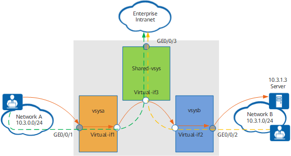
In a scenario of communication between two virtual systems across Shared-vsys, a packet is sent from the client on network A and enters vsysa. vsysa processes the packet according to the firewall forwarding process. Then the packet enters Shared-vsys, which serves as a routing device, processes the packet according to the firewall forwarding process, and forwards the packet to vsysb. vsysb then processes the packet according to the firewall forwarding process and forwards the packet to the server on network B. The detailed process is as follows:
- The client on network A initiates a connection towards the server on network B.
The first packet arrives at the FW and is sent to vsysa based on the interface. vsysa processes the packet based on the firewall forwarding process, including matching the blacklist, looking up the routing table, performing NAT, and matching a security policy. If the packet is denied at any step, vsysa discards the packet, and the process ends. If the packet passes all the steps, vsysa forwards the packet to Shared-vsys. At the same time, vsysa creates the following session for the connection:
<FW> display firewall session table verbose vsys vsysa destination global 10.3.1.3
 Current Total Sessions : 1
 icmp  VPN: vsysa --> Shared_vsys  ID: a68f42058409014faf8598d3888
 Zone: untrust --> dmz  TTL: 00:00:20  Left: 00:00:03
 Recv Interface: GigabitEthernet 0/0/1
 Interface: Virtual-if1  NextHop: 0.0.0.0
 <--packets: 1 bytes: 60 --> packets: 1 bytes: 60
 10.3.0.1:1 --> 10.3.1.3:2048 PolicyName: vsysa_to_Shared_vsys
After Virtual-if3 of Shared-vsys receives the packet, it processes the packet according to the firewall forwarding process. If the packet is denied at any step, Shared-vsys discards the packet, and the process ends. If the packet passes all the steps, Shared-vsys forwards the packet to vsysb. At the same time, Shared-vsys creates the following session for the connection.
<FW> display firewall session table verbose vsys Shared_vsys destination global 10.3.1.3
 Current Total Sessions : 1
 icmp  VPN: Shared_vsys --> vsysb  ID: a58f420584168757a3598d3888
 Zone: dmz --> dmz  TTL: 00:00:20  Left: 00:00:03
 Recv Interface: Virtual-if3
 Interface: Virtual-if3  NextHop: 0.0.0.0
 <--packets: 1 bytes: 60 --> packets: 1 bytes: 60
 10.3.0.2:1 --> 10.3.1.3:2048 PolicyName: ---
After Virtual-if2 of vsysb receives the packet, it processes the packet according to the firewall forwarding process. If the packet is denied at any step, vsysb discards the packet, and the process ends. If the packet passes all the steps, vsysb forwards the packet to the server. At the same time, vsysb creates the following session for the connection.
<FW> display firewall session table verbose vsys vsysb destination global 10.3.1.3
 Current Total Sessions : 1
 icmp  VPN: vsysb --> vsysb  ID: a68f4205842401eec62598d3888
 Zone: dmz --> untrust  TTL: 00:00:20  Left: 00:00:03
 Recv Interface: Virtual-if2
 Interface: GigabitEthernet 0/0/2  NextHop: 10.1.2.1  MAC: 0000-0201-0102
 <--packets: 1 bytes: 60 --> packets: 1 bytes: 60
 10.3.0.2:1 --> 10.3.1.3:2048 PolicyName: to_server
- The packet is forwarded through the router and arrives at the server.
The three virtual systems need to process the packet based on the firewall forwarding process. Therefore, policies and routes must be individually configured for the virtual systems.
- The key of policy configuration is to determine the source and destination security zones.
Item
Description
vsysa
Source security zone
Security zone to which the inbound interface of the packet belongs, that is, security zone to which GE0/0/1 belongs in Figure 1
Destination security zone
Security zone to which the virtual interface of vsysa belongs, that is, security zone to which Virtual-if1 belongs in Figure 1
vsysb
Source security zone
Security zone to which the virtual interface of vsysb belongs, that is, security zone to which Virtual-if2 belongs in Figure 1
Destination security zone
Security zone to which the outbound interface of the packet belongs, that is, security zone to which GE0/0/2 belongs in Figure 1
Shared-vsys
Source security zone
Security zone to which the virtual interface of Shared-vsys belongs, that is, security zone to which Virtual-if3 belongs in Figure 1
Destination security zone
Security zone to which the virtual interface of Shared-vsys belongs, that is, security zone to which Virtual-if3 belongs in Figure 1
- The following table shows the route configuration for the virtual systems.
Item
Description
vsysa
Forward route
Route to Shared-vsys. The packet is forwarded from vsysa across Shared-vsys to vsysb, you must configure the route from vsysa to Shared-vsys. The route between virtual systems can only be a static route. Different from common static routes, this static route does not need the next hop or outbound interface. Instead, you must specify Shared-vsys as the destination virtual system for the route.
For the network in Figure 1, you can configure the static route as follows:
<sysname> system-view
[sysname] ip route-static vpn-instance vsysa 10.3.1.0 255.255.255.0 vpn-instance Shared_vsys
After the configuration is complete, vsysa generates the following routing table:
[sysname] display ip routing-table vpn-instance vsysa Route Flags: R - relay, D - download to fib ------------------------------------------------------------------------------ Routing Tables: vsysa Destinations : 1 Routes : 1 Destination/Mask Proto Pre Cost Flags NextHop Interface 10.3.1.0/24 Static 60 0 D 0.0.0.0 Virtual-if3NOTE:IPv6 routing configuration does not support virtualization. When IPv6 virtual systems access each other across Shared-vsys, run the ipv6 route-static vpn-instance vsysa dest-ipv6-address prefix-length vpn-instance Shared_vsys command in the system view of the public system to configure a route from vsysa to Shared-vsys.
Return route
Route to the client. It can be a dynamic route (such as OSPF) or a static route.
For the network in Figure 1, you can configure a static route to the client as follows (10.1.1.1 is the next hop from the FW to the client):
<sysname> system-view
[sysname] switch vsys vsysa
<sysname-vsysa> system-view
[sysname-vsysa] ip route-static 10.3.0.0 255.255.255.0 10.1.1.1
NOTE:IPv6 routing configuration does not support virtualization. When IPv6 virtual systems access each other across Shared-vsys, run the ipv6 route-static vpn-instance vsysa dest-ipv6-address prefix-length interface-type interface-number [ nexthop-ipv6-address ] command in the system view of the public system to configure a route from vsysa to the client.
vsysb
Forward route
Route to the server. It can be a dynamic route (such as OSPF) or a static route.
For the network in Figure 1, you can configure a static route to the server as follows (10.1.2.1 is the next hop from the FW to the server):
<sysname> system-view
[sysname] switch vsys vsysb
<sysname-vsysb> system-view
[sysname-vsysb] ip route-static 10.3.1.0 255.255.255.0 10.1.2.1
NOTE:IPv6 routing configuration does not support virtualization. When IPv6 virtual systems access each other across Shared-vsys, run the ipv6 route-static vpn-instance vsysb dest-ipv6-address prefix-length interface-type interface-number [ nexthop-ipv6-address ] command in the system view of the public system to configure a route from vsysb to the server.
Return route
In vsysb, you do not need to configure return routes for the packets replied by the server. The reply packets from the server will match the session table of vsysb and be directly forwarded to Shared-vsys. This route configuration is different from that for forwarding within one virtual system.
Shared-vsys
Forward route
Route to vsysb. The packet is forwarded across Shared-vsys to vsysb, you must configure the route from Shared-vsys to vsysb. The route between virtual systems can only be a static route. Different from common static routes, this static route does not need the next hop or outbound interface. Instead, you must specify vsysb as the destination virtual system for the route.
For the network in Figure 1, you can configure the static route as follows:
<sysname> system-view
[sysname] ip route-static vpn-instance Shared_vsys 10.3.1.0 255.255.255.0 vpn-instance vsysb
After the configuration is complete, Shared-vsys generates the following routing table:
[sysname] display ip routing-table vpn-instance Shared_vsys Route Flags: R - relay, D - download to fib ------------------------------------------------------------------------------ Routing Tables: Shared_vsys Destinations : 1 Routes : 1 Destination/Mask Proto Pre Cost Flags NextHop Interface 10.3.1.0/24 Static 60 0 D 0.0.0.0 Virtual-if2NOTE:IPv6 routing configuration does not support virtualization. When IPv6 virtual systems access each other across Shared-vsys, run the ipv6 route-static vpn-instance Shared_vsys dest-ipv6-address prefix-length vpn-instance vsysb command in the system view of the public system to configure a route from Shared-vsys to vsysb.
Return route
In Shared-vsys, you do not need to configure return routes for the packets replied by vsysb. The reply packets from vsysb will match the session table of Shared-vsys and be directly forwarded to vsysa. This route configuration is different from that for forwarding within one virtual system.

The preceding configuration allows only the unidirectional communication from vsysa to vsysb.
If hosts in vsysb need to access hosts in vsysa, you must configure the route from vsysb to vsysa. As shown in Figure 1, run the ip route-static vpn-instance vsysb 10.3.0.0 255.255.255.0 vpn-instance Shared_vsys command on vsysb and the ip route-static vpn-instance Shared_vsys 10.3.0.0 255.255.255.0 vpn-instance vsysa command on Shared-vsys to allow hosts in vsysb to access the host at 10.3.0.3 in vsysa through Shared-vsys. In addition, you must configure a policy. The source and destination security zones in the policy are reverse to those for the access from vsysa to vsysb.