CLI: Example for Configuring a Private IPv6 Network User to Access a Private IPv4 Network Server (Access from a Virtual System to Another Through a Shared Virtual System)
Networking Requirements
As shown in Figure 1, virtual system vsysa supports IPv4/IPv6 dual stack and connects to IPv6 and IPv4 networks. It is required that a PC on the private IPv6 network be able to access a server on the public IPv4 network through domain name www.example.com and across multiple virtual systems.
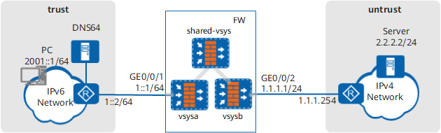

Usually, the NAT64 is deployed with the DNS64. The DNS64 performs domain name translation. The prefix and length configured for the DNS64 are the same as those of the NAT64 device.
Procedure
- Create virtual system vsysa and assign an interface and a public address to it.
# Enable the virtual system function.
<FW> system-view
[FW] vsys enable
# Create a virtual system and assign an interface and a public address to it. The public address is used in the NAT address pool.
[FW] vsys name vsysa
[FW-vsys-vsysa] assign interface GigabitEthernet 0/0/1
[FW-vsys-vsysa] assign global-ip 1.1.1.6 1.1.1.10 exclusive
[FW-vsys-vsysa] quit
- Create virtual system vsysb and assign an interface and a public address to it.
# Enable the virtual system function.
<FW> system-view
[FW] vsys enable
# Create a virtual system and assign an interface to it.
[FW] vsys name vsysb
[FW-vsys-vsysb] assign interface GigabitEthernet 0/0/2
[FW-vsys-vsysb] quit
- Create virtual system shared_vsys.
# Enable the virtual system function.
<FW> system-view
[FW] vsys enable
# Create a virtual system.
[FW] vsys name shared_vsys - Configure virtual systems to communicate in extended mode.
[FW] firewall forward cross-vsys extended - Configure IP addresses, routes, and security policies.
# Enable IPv6.
[FW] ipv6# Configure a static route to the IPv6 network.
[FW] ipv6 route-static vpn-instance vsysa 2001:: 64 1::2# Access the configuration view of virtual system vsysa.
[FW] switch vsys vsysa# Set an IP address for an interface and assign the interface to a security zone. The IP address of Virtual-if1 can be any value as long as it is not in conflict with the IP address on any other interface.
[FW-vsysa] interface GigabitEthernet 0/0/1
[FW-vsysa-GigabitEthernet0/0/1] ipv6 enable
[FW-vsysa-GigabitEthernet0/0/1] ipv6 address 1::1 64
[FW-vsysa-GigabitEthernet0/0/1] quit
[FW-vsysa] interface  Virtual-if 1
[FW-Virtual-if1] ip address 172.16.1.1 24
[FW-Virtual-if1] quit
[FW-vsysa] firewall zone trust
[FW-vsysa-zone-trust] add interface GigabitEthernet 0/0/1
[FW-vsysa-zone-trust] add interface Virtual-if 1
[FW-vsysa-zone-trust] quit
# Configure a static route to shared_vsys.
[FW-vsysa] ip route-static 2.2.2.2 32 vpn-instance shared_vsys# Configure a security policy.
[FW-vsysa] security-policy
[FW-vsysa-policy-security] rule name policy_sec_1
[FW-vsysa-policy-security-rule-policy_sec_1] source-zone trust
[FW-vsysa-policy-security-rule-policy_sec_1] destination-zone trust
[FW-vsysa-policy-security-rule-policy_sec_1] source-address 2001:: 64
[FW-vsysa-policy-security-rule-policy_sec_1] action permit
[FW-vsysa-policy-security-rule-policy_sec_1] quit
# Access the configuration view of virtual system shared_vsys.
[FW] switch vsys shared_vsys# Set an IP address for an interface and assign the interface to a security zone. The IP address can be any value as long as it does not conflict with the IP address on any other interface.
[FW-shared_vsys] interface  Virtual-if 2
[FW-Virtual-if2] ip address 172.16.2.1 24
[FW-Virtual-if2] quit
[FW-shared_vsys] firewall zone trust
[FW-shared_vsys-zone-trust] add interface Virtual-if 2
[FW-shared_vsys-zone-trust] quit
# Configure a static route to vsysb.[FW-shared_vsys] ip route-static 2.2.2.2 32 vpn-instance vsysb# Configure a security policy.
[FW-shared_vsys] security-policy
[FW-shared_vsys-policy-security] rule name policy_sec_2
[FW-shared_vsys-policy-security-rule-policy_sec_2] source-zone trust
[FW-shared_vsys-policy-security-rule-policy_sec_2] destination-zone trust
[FW-shared_vsys-policy-security-rule-policy_sec_2] source-address 1.1.1.0 24
[FW-shared_vsys-policy-security-rule-policy_sec_2] action permit
[FW-shared_vsys-policy-security-rule-policy_sec_2] quit
# Access the configuration view of virtual system vsysb.
[FW] switch vsys vsysb# Set an IP address for an interface and assign the interface to a security zone. The IP address of Virtual-if3 can be set to any address different from the IP addresses of all the other interfaces.
[FW-vsysb] interface Virtual-if 3
[FW-Virtual-if3] ip address 172.16.3.1 24
[FW-Virtual-if3] quit
[FW-vsysb] interface GigabitEthernet 0/0/2
[FW-vsysb-GigabitEthernet0/0/2] ip address 1.1.1.1 24
[FW-vsysb-GigabitEthernet0/0/2] quit
[FW-vsysb] firewall zone trust
[FW-vsysb-zone-trust] add interface Virtual-if 3
[FW-vsysb-zone-trust] quit
[FW-vsysb] firewall zone untrust
[FW-vsysb-zone-untrust] add interface GigabitEthernet 0/0/2
[FW-vsysb-zone-untrust] quit
# Configure a static route to the IPv4 network.[FW-vsysb] ip route-static 2.2.2.0 24 1.1.1.254# Configure a security policy.
[FW-vsysb] security-policy
[FW-vsysb-policy-security] rule name policy_sec_3
[FW-vsysb-policy-security-rule-policy_sec_3] source-zone trust
[FW-vsysb-policy-security-rule-policy_sec_3] destination-zone untrust
[FW-vsysb-policy-security-rule-policy_sec_3] destination-address 2.2.2.2 24
[FW-vsysb-policy-security-rule-policy_sec_3] action permit
[FW-vsysb-policy-security-rule-policy_sec_3] quit
- Configure NAT64.
# Enable the NAT64 function on the IPv6 network interface.
[FW-vsysa] interface GigabitEthernet 0/0/1
[FW-vsysa-GigabitEthernet0/0/1] nat64 enable
[FW-vsysa-GigabitEthernet0/0/1] quit
# Set the NAT64 prefix to 3001::/96.
[FW-vsysa] nat64 prefix 3001:: 96 In this example, the NAT64 prefix is 3001:: 96. If the prefix is left unconfigured, a well-known prefix is used by default.
# Configure IPv4 NAT address pool addressgroup1 and set the address range to 1.1.1.6 to 1.1.1.10. Use the addresses in the NAT address pool as the IPv4 addresses after the NAT64 processing.
[FW-vsysa] nat address-group addressgroup1
[FW-vsysa-address-group-addressgroup1] mode pat
[FW-vsysa-address-group-addressgroup1] section 1 1.1.1.6 1.1.1.10
[FW-vsysa-address-group-addressgroup1] quit
# Configure dynamic NAT64 mapping.
[FW-vsysa] nat-policy
[FW-vsysa-policy-nat] rule name policy_nat64
[FW-vsysa-policy-nat-rule-policy_nat64] nat-type nat64
[FW-vsysa-policy-nat-rule-policy_nat64] source-zone trust
[FW-vsysa-policy-nat-rule-policy_nat64] destination-zone trust
[FW-vsysa-policy-nat-rule-policy_nat64] source-address 2001:: 64
[FW-vsysa-policy-nat-rule-policy_nat64] action source-nat address-group addressgroup1
[FW-vsysa-policy-nat-rule-policy_nat64] quit
[FW-vsysa-policy-nat] quit
- Configure the DNS64 device.
# Set the IPv6 prefix of the DNS64 device to the NAT64 prefix of the FW, namely, 3001::/96.
# Configure a route from the DNS64 to the PC to ensure reachability.
- Configure the IPv6 address, route, and DNS of the PC. (The configuration methods of IPv6 addresses and routes vary with the operating systems of the PCs. The configuration methods are not described here.)
# Set the IPv6 address of the PC to 2001::1/64.
# Configure a route from the PC to the network segment 3001::/96 and set the next hop to the address of the IPv6 network egress router.
# Set the DNS address of the PC to the IPv6 address of the DNS64 device.
- Configure the IPv4 address and route of the server. (The method of setting the IPv4 address is determined by the operating system of the server. The setting method is not described here.)
# Set the IPv4 address of the server to 2.2.2.2/24.
# Configure a route from the server to the address range 1.1.1.6 to 1.1.1.10. The next hop of the route is the address of the IPv4 network egress router.
Verification
- Access www.example.com from the PC. The access succeeds.
Check NAT64 session table information.
<FW> display firewall ipv6 session table verbose vsys vsysa
 Current Total IPv6 Sessions : 1
 NAT64: icmpv6  VPN: vsysa --> vsysa  ID: a48f34fda4a30c993571015f1
 Zone: untrust --> trust TTL: 00:00:45  Left: 00:00:45
 Interface: GigabitEthernet0/0/1 NextHop: 1.1.1.254 MAC: 0000-0000-0000
 <--packets: 25 bytes: 2,600 --> packets: 25 bytes: 2,600
 2001::1.44019[1.1.1.7:2051] --> 3001::202:202.2048[2.2.2.2:2048] PolicyName: policy_sec_1
Configuration Scripts
Configuration script of the public system:
#
 ipv6
#
 vsys enable
#
vsys name vsysa 1
 assign interface GigabitEthernet0/0/1
 assign global-ip 1.1.1.6 1.1.1.10 exclusive
vsys name vsysb 2
 assign interface GigabitEthernet 0/0/2
vsys name shared_vsys
#
 ipv6 route-static vpn-instance vsysa 2001:: 64 1::2
#
 firewall forward cross-vsys extended
#
return
Configuration script of vsysa:
#
switch vsys vsysa
#
interface GigabitEthernet0/0/1
 ipv6 enable
 ipv6 address 1::1 64
 nat64 enable
#
interface  Virtual-if 1
 ip address 172.16.1.1 24
#
firewall zone trust
 set priority 85
 add interface GigabitEthernet0/0/1
 add interface Virtual-if 1
#
nat address-group addressgroup1
 mode pat
 section 1 1.1.1.6 1.1.1.10
#
 nat64 prefix 3001:: 96
#
 ip route-static 2.2.2.2 32 vpn-instance shared_vsys
#
security-policy
  rule name policy_sec_1
    source-zone trust
    destination-zone trust
    source-address 2001:: 64
    action permit
#
nat-policy
  rule name policy_nat64
    source-zone trust
    destination-zone trust
    nat-type nat64
    source-address 2001:: 64
    action source-nat address-group addressgroup1
#
return
Configuration script of shared_vsys:
#
switch vsys shared_vsys
#
interface  Virtual-if 2
 ip address 172.16.2.1 24
firewall zone trust
 set priority 85
 add interface Virtual-if 2
#
ip route-static 2.2.2.2 32 vpn-instance vsysb
#
security-policy
 rule name policy_sec_2
 source-zone trust
 destination-zone trust
 source-address 1.1.1.0 24
 action permit
#
return
Configuration script of vsysb:
#
switch vsys vsysb
#
interface  Virtual-if 3
 ip address 172.16.3.1 24
interface GigabitEthernet 0/0/2
 ip address 1.1.1.1 24
firewall zone trust
 set priority 85
 add interface Virtual-if 2
#
firewall zone untrust
 set priority 15
 add interface GigabitEthernet 0/0/2
#
ip route-static 2.2.2.0 24 1.1.1.254
#
security-policy
 rule name policy_sec_3
 source-zone trust
 destination-zone untrust
 destination-address 2.2.2.2 24
 action permit
#
return