Web: Example for Connecting to an Upstream Router (Service Traffic Diversion) and a Downstream Switch (VRRP Traffic Diversion)
This section provides an example for configuring a cluster in which devices connect to routers in upstream and switches in downstream.
Networking Requirements
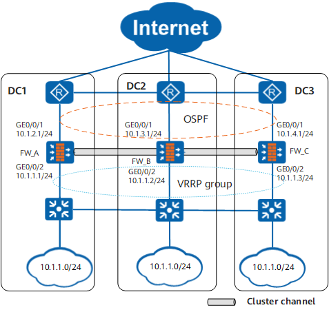
As shown in Figure 1, OSPF runs between FWs and upstream routers.
Traffic of a DC should be preferentially carried on the FW in the DC. If a FW fails, traffic can be switched to other FWs.
Data Planning
Item |
Data |
Description |
|---|---|---|
FW_A |
|
|
FW_B |
|
|
FW_C |
|
|
Procedure
- Complete basic network configurations. Configure interface
IP addresses, assign interfaces to security zones, and routes.
Perform the configuration on each cluster member. The following part is the configuration of FW_A. The configurations of FW_B and FW_C are similar.
# Assign IP addresses to interfaces.
Click GE0/0/1, set the parameters as shown in the following table, and click OK.
Zone
untrust
IPv4
IP Address
10.1.2.1/24
Configure GE0/0/2 based on the preceding step.
Zone
trust
IPv4
IP Address
10.1.1.1/24
- Click Add to create Eth-Trunk1.
Interface Name
Eth-Trunk1
Type
Aggregation Interface
Zone
dmz
Interface
GE0/0/3 and GE0/0/4
IP Address
10.1.5.1/24
Repeat the preceding steps to configure Eth-Trunk2 and Eth-Trunk3.
Interface Name
Eth-Trunk2
Type
Aggregation Interface
Zone
dmz
Interface
GE0/0/5 and GE0/0/6
IP Address
10.1.6.1/24
Interface Name
Eth-Trunk3
Type
Aggregation Interface
Zone
dmz
Interface
GE0/0/7 and GE0/0/8
IP Address
10.1.7.1/24
# Configure OSPF to ensure IP connectivity.
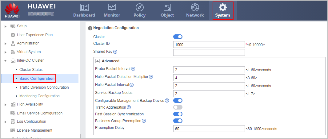
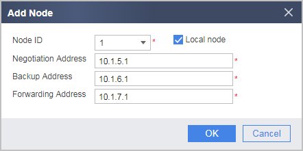
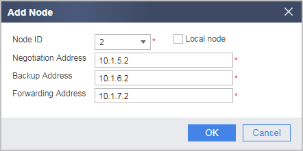
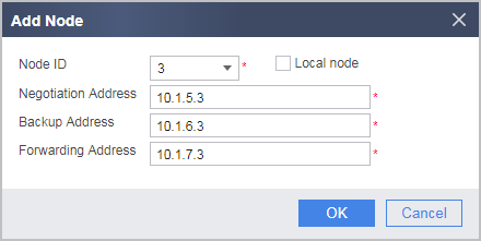
- Set cluster negotiation parameters and enable
the cluster function.
Perform the configuration on each cluster member.
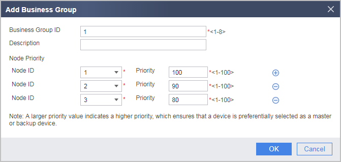
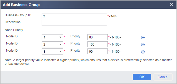
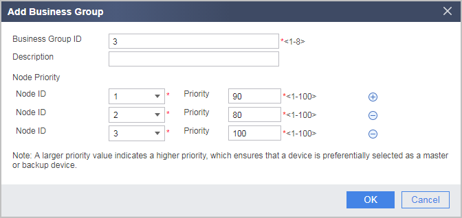
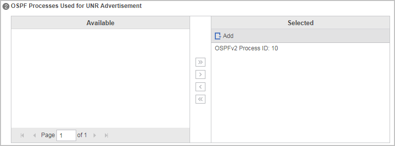
- Configure service traffic diversion and import the UNR
to OSPF.
Perform the configuration on each cluster member.
- Configure VRRP traffic diversion.
Perform the configuration on each cluster member.
# Click the VRRP Traffic Diversion tab, click Add to configure VRRP traffic diversion for each business group in sequence, and click OK.
Interface
GE0/0/2
Interface IP Address/Mask
After you select Interface, the IP address/mask of the interface is automatically displayed.
VRID
1
Virtual IP Address/Mask
10.1.1.10
Business Group ID
1
Interface
GE0/0/2
Interface IP Address/Mask
After you select Interface, the IP address/mask of the interface is automatically displayed.
VRID
2
Virtual IP Address/Mask
10.1.1.11
Business Group ID
2
Interface
GE0/0/2
Interface IP Address/Mask
After you select Interface, the IP address/mask of the interface is automatically displayed.
VRID
3
Virtual IP Address/Mask
10.1.1.12
Business Group ID
3
- Configure the cluster to track the upstream interface GE0/0/1.
Perform the configuration on each cluster member.
- Choose .
- Select GE0/0/1 from Configure Interface Monitoring and enter 1 as its weight.
- Click Add. The configuration is complete.
- Configure security policies.
Perform the following configuration on the management master device. The configuration will be automatically synchronized to other members in the cluster.
- Choose .
Click Add Security Policy to configure security policies based on the following parameter values, and click OK.
# Configure a security policy to allow intranet users to access the Internet.
Name
policy_sec1
Source Zone
trust
Destination Zone
untrust
Source Address/Region
10.1.1.0/24
Action
Permit
# Configure a security policy to allow the FW and the upstream router (in the Untrust zone) to exchange OSPF packets.
Name
policy_sec2
Source Zone
local;untrust
Destination Zone
local;untrust
Action
Permit
- Configure a NAT policy.
Perform the following configuration on the management master device. The configuration will be automatically synchronized to other members in the cluster.
- Configure routers and switches.
# Configure OSPF on the routers to advertise routes. For configuration commands, refer to the related documents of the routers.
# Add the three interfaces of the switches to the same VLANs accordingly. For configuration commands, refer to related documents of the switches.



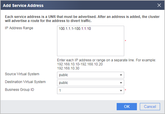
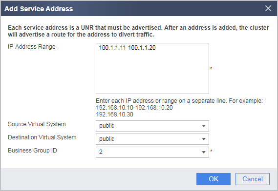
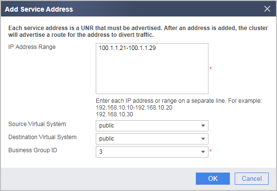
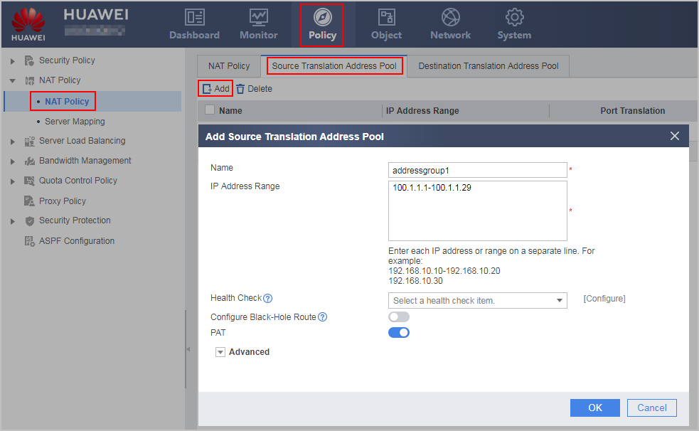
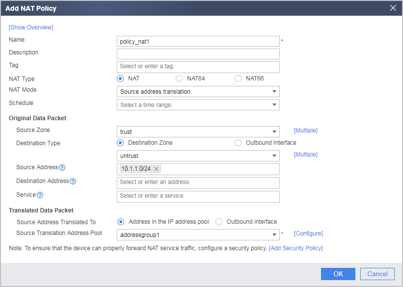
Configuration Verification
Choose to view the cluster running status.
- In normal situations, FW_A serves as the master device in business group 1; FW_B serves as the master device in business group 2; FW_C serves as the master device in business group 3.
- The ranking of business group 1 is 1 > 2 > 3; the ranking of business group 2 is 2 > 3 > 1; the ranking of business group 3 is 3 > 1 > 2.
- If FW_A fails, services can be switched to FW_B.
Configuration Script
In this example, the configurations of cluster members are almost the same. The major differences are the interface IP addresses and cluster IDs of devices.
The following part is the configuration script of FW_A. The difference content is bold. Remember to modify such parts when configuring other devices.
#
cluster id 1000
cluster detect-interval 2
cluster timer holding-multiplier 4
cluster timer hello 2
cluster backup node-num 2
cluster preempt delay 70
cluster session fast-sync enable
cluster standby config enable
cluster preempt
cluster ip-list node 1 negotiation 10.1.5.1 backup 10.1.6.1 forward 10.1.7.1
cluster ip-list node 2 negotiation 10.1.5.2 backup 10.1.6.2 forward 10.1.7.2
cluster ip-list node 3 negotiation 10.1.5.3 backup 10.1.6.3 forward 10.1.7.3
cluster node bind 1
cluster enable
#
 business-group 1
  node 1 priority 100
  node 2 priority 90
  node 3 priority 80
  ip-section 100.1.1.1 100.1.1.10
 business-group 2
  node 1 priority 80
  node 2 priority 100
  node 3 priority 90
  ip-section 100.1.1.11 100.1.1.20
 business-group 3
  node 1 priority 90
  node 2 priority 80
  node 3 priority 100
  ip-section 100.1.1.21 100.1.1.29
#
 cluster track interface GigabitEthernet 0/0/1
#
ospf 10
 import-route unr route-policy cluster_rt
 area 0.0.0.0
  network 10.1.2.0 0.0.0.255
#
firewall zone trust
 set priority 85
 add interface GigabitEthernet 0/0/2
#
firewall zone untrust
 set priority 5
 add interface GigabitEthernet 0/0/1
#
firewall zone dmz
 set priority 50
 add interface Eth-Trunk1
 add interface Eth-Trunk2
 add interface Eth-Trunk3
#
interface GigabitEthernet 0/0/1
 ip address 10.1.2.1 255.255.255.0
#
interface GigabitEthernet 0/0/2
 ip address 10.1.1.1 255.255.255.0
 vrrp vrid 1 virtual-ip 10.1.1.10 active
 vrrp vrid 2 virtual-ip 10.1.1.11 active
 vrrp vrid 3 virtual-ip 10.1.1.12 active
 vrrp vrid 1 track business-group 1
 vrrp vrid 2 track business-group 2
 vrrp vrid 3 track business-group 3
#
interface GigabitEthernet 0/0/3
 eth-trunk 1
#
interface GigabitEthernet 0/0/4
 eth-trunk 1
#
interface GigabitEthernet 0/0/5
 eth-trunk 2
#
interface GigabitEthernet 0/0/6
 eth-trunk 2
#
interface GigabitEthernet 0/0/7
 eth-trunk 3
#
interface GigabitEthernet 0/0/8
 eth-trunk 3
#
interface Eth-Trunk1
 ip address 10.1.5.1 255.255.255.0
#
interface Eth-Trunk2
 ip address 10.1.6.1 255.255.255.0
#
interface Eth-Trunk3
 ip address 10.1.7.1 255.255.255.0
#
security-policy
 rule name policy_sec1
  source-zone trust
  destination-zone untrust
  source-address 10.1.1.0 24
  action permit
 rule name policy_sec2
  source-zone local
  source-zone untrust
  destination-zone local
  destination-zone untrust
  action permit
#
nat-policy
 rule name policy_nat1
  source-zone trust
  destination-zone untrust
  source-address 10.1.1.0 255.255.255.0
  action source-nat address-group addressgroup1
#