Web: Example for Configuring Hot Standby in Active/Standby Mode Where Firewalls Connect to Switches in Out-of-path Mode and Static Routes Are Configured on the Switches to Divert Traffic to the Firewalls
This section provides an example for how to connect two FWs to core switches of a data center in out-of-path mode and configure static routes on the switches to divert traffic to the FWs.
Networking Requirements
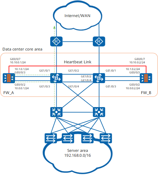
As shown in Figure 1, two FWs are connected off-line to the core switches in the data center to secure the data center network. All traffic on the core switches is diverted to the FWs based on static routes for security checks. The FWs are expected to work in active/standby mode. Normally, traffic is forwarded by FW_A. If FW_A is faulty, FW_B takes over to ensure service continuity.
Configuration Roadmap
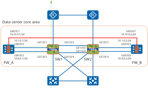
As shown in Figure 2, if the core switches need to use static routes to divert traffic to the FWs, you need to configure static routes and set the next hops to the IP addresses of the FW interfaces. However, the core switches and upstream routers and downstream aggregation switches run OSPF. Therefore, traffic cannot be diverted to the FWs after reaching the core switches. Instead, the traffic is directly forwarded to the upstream and downstream devices.
Therefore, you must configure the virtual routing and forwarding (VRF) function on the core switches to virtualize each core switch into a public switch (Public) for connecting to the upstream switch and a virtual switch (VRF) for connecting to the downstream switch. The two virtualized switches are isolated. Therefore, traffic can be diverted to the FWs.
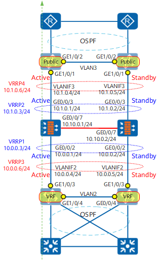
Figure 2 can be abstracted as Figure 3. The FWs run static routes with upstream and downstream switches (Public and VRF). Therefore, you need to configure VRRP groups on the FWs and switches for them to communicate using the virtual IP addresses of VRRP groups.
As shown in Figure 3, configure static routes on the FWs and set the next hops to the IP addresses of VRRP groups 3 and 4. Configure a static route on the Public switch and set the next hop to the IP address of VRRP group 2. Configure a static route on the VRF switch and set the next hop to the IP address of VRRP group 1.

The core switches run static routes with the FWs and OSPF with other devices. Figure 3 lists only the core switch interfaces related to the FWs.
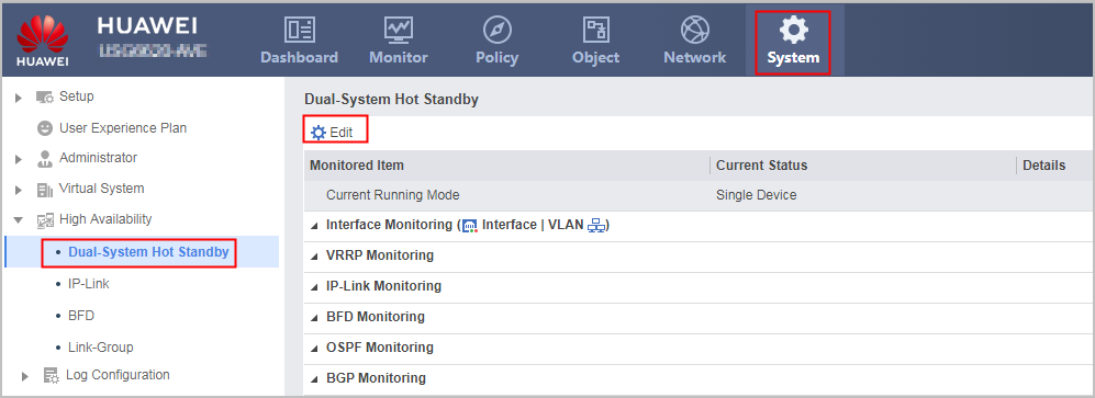
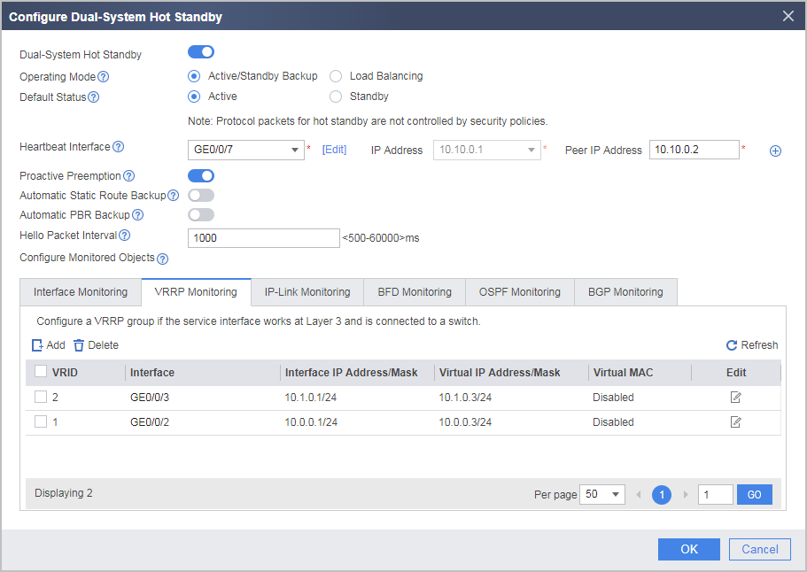
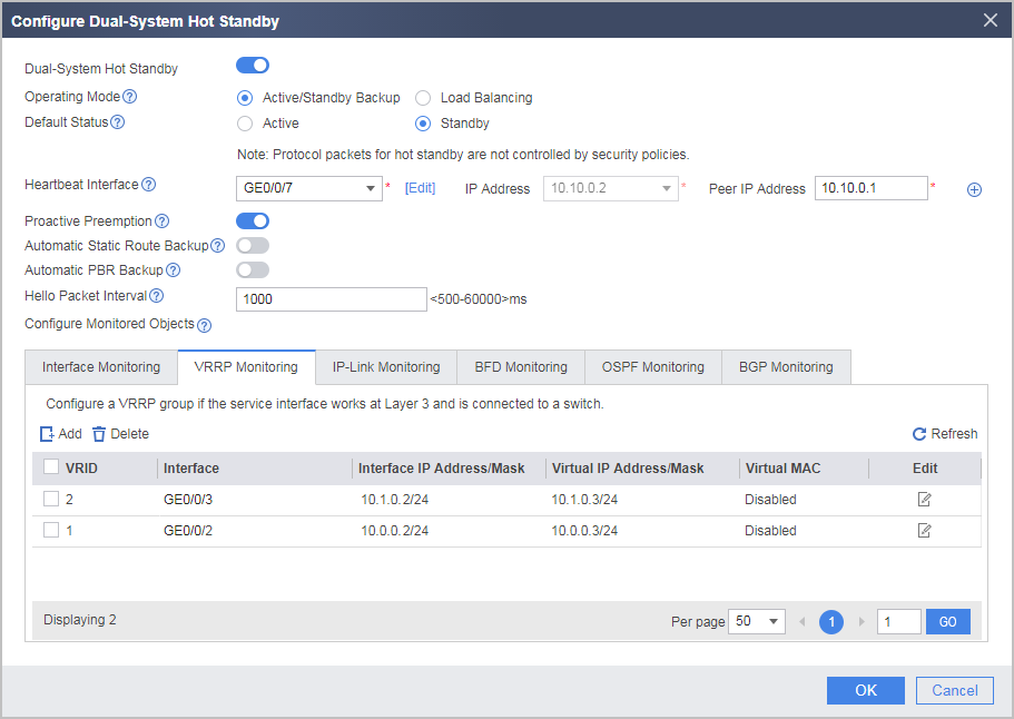
Specify GE0/0/7 on the FW as the heartbeat interface and enable hot standby.
Configure security functions, such as security policies, IPS, and attack defense, on FW_A. FW_A will automatically synchronize its configurations to FW_B. This section describes only security policy configurations as an example.
Procedure
- Set interface IP addresses and assign the interfaces to security zones.
# This section uses the configurations on FW_A as an example. The configurations on FW_B are the same as those on FW_A.
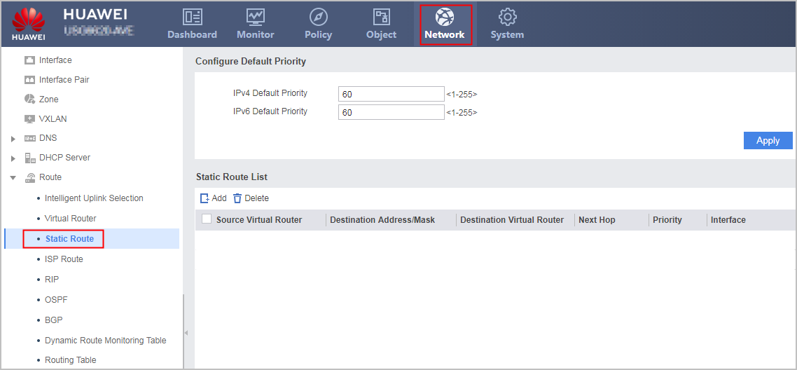
- Create static routes.
# This section uses the configurations on FW_A as an example. The configurations on FW_B are the same as those on FW_A.
- Choose .
- Choose .
- Configure hot standby.
- Configure a security policy.
Configure a security policy on FW_A to allow Internet users to access the server area (subnet: 192.168.0.0/16, port: 80) in the data center. Security policies configured on FW_A will be automatically backed up to FW_B.
- Configure the core switches.
This example describes only the switch configurations related to firewall connection.
# Configure Switch1.
[Switch1] ip vpn-instance VRF     //Create VRF.
[Switch1-vpn-instance-VRF] ipv4-family
[Switch1-vpn-instance-VRF-af-ipv4] route-distinguisher 100:1
[Switch1-vpn-instance-VRF-af-ipv4] vpn-target 111:1 both
[Switch1-vpn-instance-VRF-af-ipv4] quit
[Switch1-vpn-instance-VRF] quit
[Switch1] vlan 2
[Switch1-vlan2] port gigabitethernet 1/0/3 to 1/0/4     //Add the interface to VLAN2.
[Switch1-vlan2] quit
[Switch1] interface Vlanif 2
[Switch1-Vlanif2] ip binding vpn-instance VRF     //Bind VLANIF2 to VRF.
[Switch1-Vlanif2] ip address 10.0.0.4 24
[Switch1-Vlanif2] vrrp vrid 3 virtual-ip 10.0.0.6     //Create VRRP group 3.
[Switch1-Vlanif2] vrrp vrid 3 priority 120     //Set the priority to 120. The VRRP group with high priority is active.
[Switch1-Vlanif2] quit
[Switch1] vlan 3
[Switch1-vlan3] port gigabitethernet 1/0/1 to 1/0/2     //Add the interface to VLAN3.
[Switch1-vlan3] quit
[Switch1] interface Vlanif 3
[Switch1-Vlanif3] ip address 10.1.0.4 24
[Switch1-Vlanif3] vrrp vrid 4 virtual-ip 10.1.0.6     //Create VRRP group 4.
[Switch1-Vlanif3] vrrp vrid 4 priority 120     //Set the priority to 120. The VRRP group with high priority is active.
[Switch1-Vlanif3] quit
[Switch1] ip route-static vpn-instance VRF 0.0.0.0 0.0.0.0 10.0.0.3    //Configure a default route on the VRF and set the next hop to the virtual IP address of VRRP group 1.
[Switch1] ip route-static 192.168.0.0 255.255.0.0 10.1.0.3    //Configure a static route on the Public switch and set the next hop to the virtual IP address of VRRP group 2.
# Configure Switch2.
[Switch2] ip vpn-instance VRF     //Create VRF.
[Switch2-vpn-instance-VRF] ipv4-family
[Switch2-vpn-instance-VRF-af-ipv4] route-distinguisher 100:1
[Switch2-vpn-instance-VRF-af-ipv4] vpn-target 111:1 both
[Switch2-vpn-instance-VRF-af-ipv4] quit
[Switch2-vpn-instance-VRF] quit
[Switch2] vlan 2
[Switch2-vlan2] port gigabitethernet 1/0/3 to 1/0/4     //Add the interface to VLAN2.
[Switch2-vlan2] quit
[Switch2] interface Vlanif 2
[Switch2-Vlanif2] ip binding vpn-instance VRF     //Bind VLANIF2 to VRF.
[Switch2-Vlanif2] ip address 10.0.0.5 24
[Switch2-Vlanif2] vrrp vrid 3 virtual-ip 10.0.0.6     //Create VRRP group 3.
[Switch2-Vlanif2] vrrp vrid 3 priority 100     //Set the priority to 100. The VRRP group with low priority is standby.
[Switch2-Vlanif2] quit
[Switch2] vlan 3
[Switch2-vlan3] port gigabitethernet 1/0/1 to 1/0/2     //Add the interface to VLAN3.
[Switch2-vlan3] quit
[Switch2] interface Vlanif 3
[Switch2-Vlanif3] ip address 10.1.0.5 24
[Switch2-Vlanif3] vrrp vrid 4 virtual-ip 10.1.0.6     //Create VRRP group 4.
[Switch2-Vlanif3] vrrp vrid 4 priority 100     //Set the priority to 100. The VRRP group with low priority is standby.
[Switch2-Vlanif3] quit
[Switch2] ip route-static vpn-instance VRF 0.0.0.0 0.0.0.0 10.0.0.3    //Configure a default route on the VRF and set the next hop to the virtual IP address of VRRP group 1.
[Switch2] ip route-static 192.168.0.0 255.255.0.0 10.1.0.3    //Configure a static route on the Public switch and set the next hop to the virtual IP address of VRRP group 2.
Configuration Scripts
FW_A |
FW_B |
|---|---|
# hrp enable hrp interface GigabitEthernet 0/0/7 remote 10.10.0.2 # interface GigabitEthernet 0/0/2 ip address 10.0.0.1 255.255.255.0 vrrp vrid 1 virtual-ip 10.0.0.3 active # interface GigabitEthernet 0/0/3 ip address 10.1.0.1 255.255.255.0 vrrp vrid 2 virtual-ip 10.1.0.3 active # interface GigabitEthernet 0/0/7 ip address 10.10.0.1 255.255.255.0 # firewall zone trust set priority 85 add interface GigabitEthernet 0/0/2 # firewall zone dmz set priority 50 add interface GigabitEthernet0/0/7 # firewall zone untrust set priority 5 add interface GigabitEthernet 0/0/3 # ip route-static 0.0.0.0 0.0.0.0 10.1.0.6 ip route-static 192.168.0.0 255.255.0.0 10.0.0.6 # security-policy rule name policy_sec1 source-zone untrust destination-zone trust destination-address 192.168.0.0 16 service http action permit |
# hrp enable hrp interface GigabitEthernet 0/0/7 remote 10.10.0.1 # interface GigabitEthernet 0/0/2 ip address 10.0.0.2 255.255.255.0 vrrp vrid 1 virtual-ip 10.0.0.3 standby # interface GigabitEthernet 0/0/3 ip address 10.1.0.2 255.255.255.0 vrrp vrid 2 virtual-ip 10.1.0.3 standby # interface GigabitEthernet 0/0/7 ip address 10.10.0.2 255.255.255.0 # firewall zone trust set priority 85 add interface GigabitEthernet 0/0/2 # firewall zone dmz set priority 50 add interface GigabitEthernet0/0/7 # firewall zone untrust set priority 5 add interface GigabitEthernet 0/0/3 # ip route-static 0.0.0.0 0.0.0.0 10.1.0.6 ip route-static 192.168.0.0 255.255.0.0 10.0.0.6 # security-policy rule name policy_sec1 source-zone untrust destination-zone trust destination-address 192.168.0.0 16 service http action permit |