CLI: Example for Configuring Hot Standby in Active/Standby Mode Where Firewalls Are Deployed in In-path Mode and Connect to Routers Through OSPF in the Upstream Direction and Switches in the Downstream Direction
This section provides a CLI example of configuring hot standby in active/standby mode in which the service interfaces of the firewalls work at Layer 3 and connect to routers through OSPF in the upstream direction and switches in the downstream direction.
Networking Requirements
As shown in Figure 1, the service interfaces of the FWs work at Layer 3 and are connected to upstream routers and downstream switches. OSPF runs between the FWs and upstream routers.
The FWs are expected to work in active/standby mode. Normally, traffic is forwarded by FW_A. If FW_A is faulty, FW_B takes over to ensure service continuity.
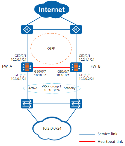
Procedure
- Complete basic network configurations.
FW_A
FW_B
# Set IP addresses for the interfaces on FWs.
<FW_A> system-view
[FW_A] interface GigabitEthernet 0/0/1
[FW_A-GigabitEthernet0/0/1] ip address 10.2.0.1 24
[FW_A-GigabitEthernet0/0/1] quit
[FW_A] interface GigabitEthernet 0/0/3
[FW_A-GigabitEthernet0/0/3] ip address 10.3.0.1 24
[FW_A-GigabitEthernet0/0/3] quit
[FW_A] interface GigabitEthernet 0/0/7
[FW_A-GigabitEthernet0/0/7] ip address 10.10.0.1 24
[FW_A-GigabitEthernet0/0/7] quit
<FW_B> system-view
[FW_B] interface GigabitEthernet 0/0/1
[FW_B-GigabitEthernet0/0/1] ip address 10.2.1.1 24
[FW_B-GigabitEthernet0/0/1] quit
[FW_B] interface GigabitEthernet 0/0/3
[FW_B-GigabitEthernet0/0/3] ip address 10.3.0.2 24
[FW_B-GigabitEthernet0/0/3] quit
[FW_B] interface GigabitEthernet 0/0/7
[FW_B-GigabitEthernet0/0/7] ip address 10.10.0.2 24
[FW_B-GigabitEthernet0/0/7] quit
# Assign the interfaces to security zones on FWs.
[FW_A] firewall zone trust
[FW_A-zone-trust] add interface GigabitEthernet 0/0/3
[FW_A-zone-trust] quit
[FW_A] firewall zone dmz
[FW_A-zone-dmz] add interface GigabitEthernet 0/0/7
[FW_A-zone-dmz] quit
[FW_A] firewall zone untrust
[FW_A-zone-untrust] add interface GigabitEthernet 0/0/1
[FW_A-zone-untrust] quit
[FW_B] firewall zone trust
[FW_B-zone-trust] add interface GigabitEthernet 0/0/3
[FW_B-zone-trust] quit
[FW_B] firewall zone dmz
[FW_B-zone-dmz] add interface GigabitEthernet 0/0/7
[FW_B-zone-dmz] quit
[FW_B] firewall zone untrust
[FW_B-zone-untrust] add interface GigabitEthernet 0/0/1
[FW_B-zone-untrust] quit
# Configure OSPF to ensure IP connectivity on FWs.
[FW_A] ospf 10
[FW_A-ospf-10] area 0
[FW_A-ospf-10-area-0.0.0.0] network 10.2.0.0 0.0.0.255
[FW_A-ospf-10-area-0.0.0.0] network 10.3.0.0 0.0.0.255
[FW_A-ospf-10-area-0.0.0.0] quit
[FW_A-ospf-10] quit
[FW_B] ospf 10
[FW_B-ospf-10] area 0
[FW_B-ospf-10-area-0.0.0.0] network 10.2.1.0 0.0.0.255
[FW_B-ospf-10-area-0.0.0.0] network 10.3.0.0 0.0.0.255
[FW_B-ospf-10-area-0.0.0.0] quit
[FW_B-ospf-10] quit
- Configure hot standby.
In this example, the upstream device is a router, the downstream device is a switch, and service interfaces on the FWs work at Layer 3, you need to configure a VGMP group on FWs to monitor the upstream interface and configure a VRRP group on the downstream interface.
FW_A
FW_B
# Configure a VGMP group on FWs to monitor the upstream interface and configure a VRRP group on the downstream interface.
[FW_A] hrp track interface GigabitEthernet 0/0/1
[FW_B] hrp track interface GigabitEthernet 0/0/1
# Configure VRRP group 1 on downstream service interface GE0/0/3 of FW_A and set the VRRP group status to Active. Configure VRRP group 1 on downstream service interface GE0/0/3 of FW_B and set the VRRP group status to Standby.
[FW_A] interface GigabitEthernet 0/0/3
[FW_A-GigabitEthernet0/0/3] vrrp vrid 1 virtual-ip 10.3.0.3 active
[FW_A-GigabitEthernet0/0/3] quit
[FW_B] interface GigabitEthernet 0/0/3
[FW_B-GigabitEthernet0/0/3] vrrp vrid 1 virtual-ip 10.3.0.3 standby
[FW_B-GigabitEthernet0/0/3] quit
# Configure the function of adjusting the OSPF cost based on VGMP status on FWs.
[FW_A] hrp adjust ospf-cost enable[FW_B] hrp adjust ospf-cost enable# Specify the heartbeat interface and enable hot standby on FWs.
[FW_A] hrp interface GigabitEthernet 0/0/7 remote 10.10.0.2
[FW_A] hrp enable
[FW_B] hrp interface GigabitEthernet 0/0/7 remote 10.10.0.1
[FW_B] hrp enable
- Create security policies on FW_A. After hot standby relationship is established, the security policies on FW_A will be automatically backed up to FW_B.
# Configure a security policy to allow intranet users to access the Internet.
HRP_M[FW_A] security-policy
HRP_M[FW_A-policy-security] rule name policy_sec1
HRP_M[FW_A-policy-security-rule-policy_sec1] source-zone trust
HRP_M[FW_A-policy-security-rule-policy_sec1] destination-zone untrust
HRP_M[FW_A-policy-security-rule-policy_sec1] source-address 10.3.0.0 24
HRP_M[FW_A-policy-security-rule-policy_sec1] action permit
HRP_M[FW_A-policy-security-rule-policy_sec1] quit
# Configure a security policy to allow FW_A and the upstream router (in the untrust zone) to exchange OSPF packets.

Controlling function of security policies for OSPF packets are configured by the firewall packet-filter basic-protocol enable command. By default, the function of the firewall packet-filter basic-protocol enable command is enabled. That is, OSPF packets are controlled by security policies. In this case, a security policy must be configured between the untrust zone where the upstream service interface resides and the local zone to allow OSPF packets to pass. In this example, enabling the firewall packet-filter basic-protocol enable command is used as an example.
HRP_M[FW_A-policy-security] rule name policy_sec2
HRP_M[FW_A-policy-security-rule-policy_sec2] source-zone local untrust
HRP_M[FW_A-policy-security-rule-policy_sec2] destination-zone local untrust
HRP_M[FW_A-policy-security-rule-policy_sec2] service ospf
HRP_M[FW_A-policy-security-rule-policy_sec2] action permit
- Configure the routers and switches.
# Configure OSPF on the routers to advertise routes. For configuration commands, refer to the related documents of the routers.
# Add the three interfaces of the switches to the same VLANs accordingly. For configuration commands, refer to related documents of the switches.
Verification
Run the display vrrp command on FW_A and FW_B to check the status information about the interfaces in the VRRP group. If the following information is displayed, the VRRP group is successfully created.
FW_A
FW_B
HRP_M<FW_A> display vrrp
 GigabitEthernet0/0/3 | Virtual Router 1
    State : Master
    Virtual IP : 10.3.0.3
    Master IP : 10.3.0.1
    PriorityRun : 120
    PriorityConfig : 100
    MasterPriority : 120
    Preempt : YES   Delay Time : 0 s
    TimerRun : 60 s
    TimerConfig : 60 s
    Auth type : NONE
    Virtual MAC : 0000-5e00-0101
    Check TTL : YES
    Config type : vgmp-vrrp
    Backup-forward : disabled
    Create time : 2018-03-17 17:35:54 UTC+08:00
    Last change time : 2018-03-22 16:01:56 UTC+08:00
HRP_S<FW_B> display vrrp
 GigabitEthernet0/0/3 | Virtual Router 1
    State : Backup
    Virtual IP : 10.3.0.3
    Master IP : 10.3.0.1
    PriorityRun : 120
    PriorityConfig : 100
    MasterPriority : 120
    Preempt : YES   Delay Time : 0 s
    TimerRun : 60 s
    TimerConfig : 60 s
    Auth type : NONE
    Virtual MAC : 0000-5e00-0101
    Check TTL : YES
    Config type : vgmp-vrrp
    Backup-forward : disabled
    Create time : 2018-03-17 17:37:54 UTC+08:00
    Last change time : 2018-03-22 16:03:56 UTC+08:00
Run the display hrp state verbose command on FW_A and FW_B to check the VGMP group status. If the following information is displayed, hot standby relationship is successfully established.
FW_A
FW_B
HRP_M<FW_A> display hrp state verbose
 Role: active, peer: standby
 Running priority: 45000, peer: 45000
 Backup channel usage: 30%
 Stable time: 1 days, 13 hours, 35 minutes
 Last state change information: 2018-03-22 16:01:56 HRP core state changed, old_
state = normal(standby), new_state = normal(active), local_priority = 45000,
 peer_priority = 45000.

 Configuration:
 hello interval:              1000ms
 preempt:                     60s
 mirror configuration:        off
 mirror session:              off
 track trunk member:          on
 auto-sync configuration:     on
 auto-sync connection-status: on
 adjust ospf-cost:            on
 adjust ospfv3-cost:          on
 adjust bgp-cost:             on
 nat resource:                off

 Detail information:
          GigabitEthernet0/0/3 vrrp vrid 1: active
                      GigabitEthernet0/0/1: up
                                  ospf-cost: +0
HRP_S<FW_B> display hrp state verbose
 Role: standby, peer: active
 Running priority: 45000, peer: 45000
 Backup channel usage: 30%
 Stable time: 1 days, 13 hours, 35 minutes
 Last state change information: 2018-03-22 16:03:56 HRP core state changed, old_
state = normal(standby), new_state = normal(standby), local_priority = 45000,
 peer_priority = 45000.

 Configuration:
 hello interval:              1000ms
 preempt:                     60s
 mirror configuration:        off
 mirror session:              off
 track trunk member:          on
 auto-sync configuration:     on
 auto-sync connection-status: on
 adjust ospf-cost:            on
 adjust ospfv3-cost:          on
 adjust bgp-cost:             on
 nat resource:                off

 Detail information:
           GigabitEthernet0/0/3 vrrp vrid 1: standby
                       GigabitEthernet0/0/1: up
                                  ospf-cost: +65500
Configuration Scripts
FW_A |
FW_B |
|---|---|
# hrp enable hrp interface GigabitEthernet 0/0/7 remote 10.10.0.2 hrp track interface GigabitEthernet 0/0/1 # interface GigabitEthernet 0/0/1 ip address 10.2.0.1 255.255.255.0 # interface GigabitEthernet 0/0/3 ip address 10.3.0.1 255.255.255.0 vrrp vrid 1 virtual-ip 10.3.0.3 active # interface GigabitEthernet 0/0/7 ip address 10.10.0.1 255.255.255.0 # firewall zone trust set priority 85 add interface GigabitEthernet 0/0/3 # firewall zone untrust set priority 5 add interface GigabitEthernet 0/0/1 # firewall zone dmz set priority 50 add interface GigabitEthernet0/0/7 # ospf 10 area 0.0.0.0 network 10.2.0.0 0.0.0.255 network 10.3.0.0 0.0.0.255 # security-policy rule name policy_sec1 source-zone trust destination-zone untrust source-address 10.3.0.0 24 action permit rule name policy_sec2 source-zone local source-zone untrust destination-zone local destination-zone untrust service ospf action permit |
# hrp enable hrp interface GigabitEthernet 0/0/7 remote 10.10.0.1 hrp track interface GigabitEthernet 0/0/1 # interface GigabitEthernet 0/0/1 ip address 10.2.1.1 255.255.255.0 # interface GigabitEthernet 0/0/3 ip address 10.3.0.2 255.255.255.0 vrrp vrid 1 virtual-ip 10.3.0.3 standby # interface GigabitEthernet 0/0/7 ip address 10.10.0.2 255.255.255.0 # firewall zone trust set priority 85 add interface GigabitEthernet 0/0/3 # firewall zone untrust set priority 5 add interface GigabitEthernet 0/0/1 # firewall zone dmz set priority 50 add interface GigabitEthernet0/0/7 # ospf 10 area 0.0.0.0 network 10.2.1.0 0.0.0.255 network 10.3.0.0 0.0.0.255 # security-policy rule name policy_sec1 source-zone trust destination-zone untrust source-address 10.3.0.0 24 action permit rule name policy_sec2 source-zone local source-zone untrust destination-zone local destination-zone untrust service ospf action permit |