CLI: Example for Configuring Hot Standby in Active/Standby Mode Where Firewalls connect to Switches Transparently in Upstream and Downstream Directions
This section provides a CLI example of configuring hot standby in active/standby mode in which the service interfaces of the firewalls work at Layer 2 and connect to switches in upstream and downstream directions.
Networking Requirements
On the network shown in Figure 1, the service interfaces of two FWs work at Layer 2 and are directly connected to switches. The uplink and downlink service interfaces of each FW are added to VLAN10 and VLAN20. The FWs are expected to work in active/standby mode. Normally, traffic is forwarded by FW_A. When FW_A goes faulty, FW_B takes over.
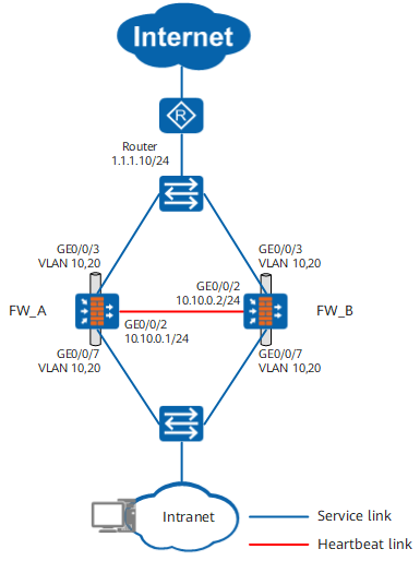
Procedure
- Complete basic network configurations.
FW_A
FW_B
# On FW_A, use the upstream and downstream service interfaces as Layer-2 interfaces and add them to the VLAN 10 and VLAN 20. On FW_B, use the upstream and downstream service interfaces as Layer-2 interfaces and add them to the VLAN 10 and VLAN 20.
[FW_A] vlan batch 10 20
[FW_A] interface GigabitEthernet 0/0/3
[FW_A-GigabitEthernet0/0/3] portswitch
[FW_A-GigabitEthernet0/0/3] port link-type trunk
[FW_A-GigabitEthernet0/0/3] port trunk allow-pass vlan 10 20
[FW_A-GigabitEthernet0/0/3] undo port trunk allow-pass vlan 1
[FW_A-GigabitEthernet0/0/3] quit
[FW_A] interface GigabitEthernet 0/0/7
[FW_A-GigabitEthernet0/0/7] portswitch
[FW_A-GigabitEthernet0/0/7] port link-type trunk
[FW_A-GigabitEthernet0/0/7] port trunk allow-pass vlan 10 20
[FW_A-GigabitEthernet0/0/7] undo port trunk allow-pass vlan 1
[FW_A-GigabitEthernet0/0/7] quit
[FW_B] vlan batch 10 20
[FW_B] interface GigabitEthernet 0/0/3
[FW_B-GigabitEthernet0/0/3] portswitch
[FW_B-GigabitEthernet0/0/3] port link-type trunk
[FW_B-GigabitEthernet0/0/3] port trunk allow-pass vlan 10 20
[FW_B-GigabitEthernet0/0/3] undo port trunk allow-pass vlan 1
[FW_B-GigabitEthernet0/0/3] quit
[FW_B] interface GigabitEthernet 0/0/7
[FW_B-GigabitEthernet0/0/7] portswitch
[FW_B-GigabitEthernet0/0/7] port link-type trunk
[FW_B-GigabitEthernet0/0/7] port trunk allow-pass vlan 10 20
[FW_B-GigabitEthernet0/0/7] undo port trunk allow-pass vlan 1
[FW_B-GigabitEthernet0/0/7] quit
# Set an IP address for the heartbeat interface on FWs.
[FW_A] interface GigabitEthernet 0/0/2
[FW_A-GigabitEthernet0/0/2] ip address 10.10.0.1 24
[FW_A-GigabitEthernet0/0/2] quit
[FW_B] interface GigabitEthernet 0/0/2
[FW_B-GigabitEthernet0/0/2] ip address 10.10.0.2 24
[FW_B-GigabitEthernet0/0/2] quit
# Assign the interfaces to security zones on FWs.
[FW_A] firewall zone trust
[FW_A-zone-trust] add interface GigabitEthernet 0/0/7
[FW_A-zone-trust] quit
[FW_A] firewall zone dmz
[FW_A-zone-dmz] add interface GigabitEthernet 0/0/2
[FW_A-zone-dmz] quit
[FW_A] firewall zone untrust
[FW_A-zone-untrust] add interface GigabitEthernet 0/0/3
[FW_A-zone-untrust] quit
[FW_B] firewall zone trust
[FW_B-zone-trust] add interface GigabitEthernet 0/0/7
[FW_B-zone-trust] quit
[FW_B] firewall zone dmz
[FW_B-zone-dmz] add interface GigabitEthernet 0/0/2
[FW_B-zone-dmz] quit
[FW_B] firewall zone untrust
[FW_B-zone-untrust] add interface GigabitEthernet 0/0/3
[FW_B-zone-untrust] quit
- Configure hot standby.
FW_A
FW_B
# Configure a VGMP group to monitor the VLANs on FW_A. Configure a VGMP group to monitor the VLANs on FW_B, and configure on FW_B as the standby FW.
[FW_A] hrp track vlan 10
[FW_A] hrp track vlan 20
[FW_B] hrp track vlan 10
[FW_B] hrp track vlan 20
[FW_B] hrp standby-device
# Specify the heartbeat interface and enable hot standby on FWs.
[FW_A] hrp interface GigabitEthernet 0/0/2 remote 10.10.0.2
[FW_A] hrp enable
[FW_B] hrp interface GigabitEthernet 0/0/2 remote 10.10.0.1
[FW_B] hrp enable
- Create a security policy on FW_A. After hot standby relationship is established, the security policy on FW_A will be automatically backed up to FW_B.
HRP_M[FW_A] security-policy
HRP_M[FW_A-policy-security] rule name policy_sec1
HRP_M[FW_A-policy-security-rule-policy_sec1] source-zone trust
HRP_M[FW_A-policy-security-rule-policy_sec1] destination-zone untrust
HRP_M[FW_A-policy-security-rule-policy_sec1] action permit
- Configure the switches.
Add the three interfaces of the switches to the same VLANs accordingly. For configuration commands, refer to related documents of the switches.
Verification
# Run the display hrp state verbose command on FW_A and FW_B to check the VGMP group status. If the following information is displayed, hot standby relationship is successfully established.
FW_A |
FW_B |
|---|---|
HRP_M<FW_A> display hrp state verbose Role: active, peer: standby Running priority: 45000, peer: 45000 Backup channel usage: 0.38% Stable time: 0 days, 7 hours, 30 minutes Last state change information: 2019-04-16 11:13:54 HRP core state changed, old_ state = abnormal(standby), new_state = normal, local_priority = 45000, peer_prio rity = 45000. Configuration: hello interval: 1000ms preempt: 60s mirror configuration: off mirror session: off track trunk member: on auto-sync configuration: on auto-sync connection-status: on adjust ospf-cost: on adjust ospfv3-cost: on adjust bgp-cost: on nat resource: off Detail information: GigabitEthernet0/0/3: up GigabitEthernet0/0/7: up vlan 10: enabled vlan 20: enabled ospf-cost: +0 ospfv3-cost: +0 bgp-cost: +0 |
HRP_S<FW_B> display hrp state verbose Role: standby, peer: active Running priority: 45000, peer: 45000 Backup channel usage: 0.38% Stable time: 0 days, 5 hours, 47 minutes Last state change information: 2019-04-16 11:10:14 HRP link changes to up. Configuration: hello interval: 1000ms preempt: 60s mirror configuration: off mirror session: off track trunk member: on auto-sync configuration: on auto-sync connection-status: on adjust ospf-cost: on adjust ospfv3-cost: on adjust bgp-cost: on nat resource: off Detail information: GigabitEthernet0/0/3: up GigabitEthernet0/0/7: up vlan 10: disabled vlan 20: disabled ospf-cost: +0 ospfv3-cost: +0 bgp-cost: +0 |
Configuration Scripts
FW_A |
FW_B |
|---|---|
# sysname FW_A # vlan batch 10 20 # hrp enable hrp interface GigabitEthernet0/0/2 remote 10.10.0.2 hrp track vlan 10 hrp track vlan 20 # interface GigabitEthernet0/0/3 portswitch port link-type trunk port trunk allow-pass vlan 10 20 undo port trunk allow-pass vlan 1 # interface GigabitEthernet0/0/7 portswitch port link-type trunk port trunk allow-pass vlan 10 20 undo port trunk allow-pass vlan 1 # interface GigabitEthernet0/0/2 ip address 10.10.0.1 255.255.255.0 # firewall zone trust set priority 85 add interface GigabitEthernet0/0/7 # firewall zone untrust set priority 5 add interface GigabitEthernet0/0/3 # firewall zone dmz set priority 50 add interface GigabitEthernet0/0/2 # security-policy rule name policy_sec source-zone trust destination-zone untrust action permit |
# sysname FW_B # vlan batch 10 20 # hrp enable hrp interface GigabitEthernet0/0/2 remote 10.10.0.1 hrp track vlan 10 hrp track vlan 20 hrp standby-device # interface GigabitEthernet0/0/3 portswitch port link-type trunk port trunk allow-pass vlan 10 20 undo port trunk allow-pass vlan 1 # interface GigabitEthernet0/0/7 portswitch port link-type trunk port trunk allow-pass vlan 10 20 undo port trunk allow-pass vlan 1 # interface GigabitEthernet0/0/2 ip address 10.10.0.2 255.255.255.0 # firewall zone trust set priority 85 add interface GigabitEthernet0/0/7 # firewall zone untrust set priority 5 add interface GigabitEthernet0/0/3 # firewall zone dmz set priority 50 add interface GigabitEthernet0/0/2 # security-policy rule name policy_sec source-zone trust destination-zone untrust action permit |