CLI: Example for Configuring Hot Standby (Active/Standby) of Virtual Systems on Firewalls Connecting to Switches in Upstream and Downstream Directions
This section provides a CLI example of how to configure hot standby in active/standby mode in which the service interfaces of each FW work at Layer 3 and connect to switches after virtual systems are configured on the FW.
Networking Requirements
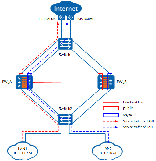
As shown in Figure 1, two network segments on the enterprise network need to be separated. Switch1 and Switch2 use VLANs to separate the two network segments, and the FWs use virtual systems to separate them. The two FWs work in active/standby mode. In normal situations, FW_A forwards traffic. When FW_A fails, traffic is forwarded by FW_B. This ensures that the services are not interrupted.
Data Planning
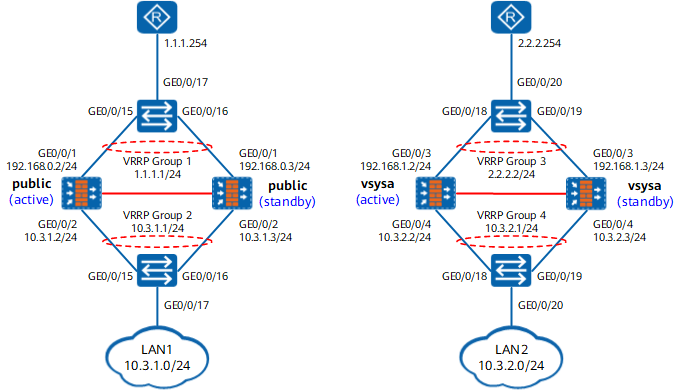
Item |
Data |
Description |
|---|---|---|
Interfaces |
Interface number: GigabitEthernet 0/0/1 IP address: 192.168.0.2/24 Security zone: untrust |
Public interface of the root system |
Interface number: GigabitEthernet 0/0/2 IP address: 10.3.1.2/24 Security zone: trust |
Private interface of the public system |
|
Interface number: GigabitEthernet 0/0/3 IP address: 192.168.1.2/24 Security zone: untrust |
Public interface of virtual system vsysa |
|
Interface number: GigabitEthernet 0/0/4 IP address: 10.3.2.2/24 Security zone: trust |
Private interface of virtual system vsysa |
|
Interface number: GigabitEthernet 0/0/7 IP address: 10.10.0.1/24 Security zone: DMZ |
Heartbeat interface |
|
VRRP groups |
VRRP group 1: 1.1.1.1/24 active |
- |
VRRP group 2: 10.3.1.1/24 active |
- |
|
VRRP group 3: 2.2.2.2/24 active |
- |
|
VRRP group 4: 10.3.2.1/24 active |
- |
|
Routes |
Destination IP address: 0.0.0.0 Next hop: 1.1.1.254 |
Default route of the public system |
Destination IP address: 0.0.0.0 Next hop: 2.2.2.254 |
Default route of virtual system vsysa |
Item |
Data |
Description |
|---|---|---|
Interfaces |
Interface number: GigabitEthernet 0/0/1 IP address: 192.168.0.3/24 Security zone: untrust |
Public interface of the public system |
Interface number: GigabitEthernet 0/0/2 IP address: 10.3.1.3/24 Security zone: trust |
Private interface of the public system |
|
Interface number: GigabitEthernet 0/0/3 IP address: 192.168.1.3/24 Security zone: untrust |
Public interface of virtual system vsysa |
|
Interface number: GigabitEthernet 0/0/4 IP address: 10.3.2.3/24 Security zone: trust |
Private interface of virtual system vsysa |
|
Interface number: GigabitEthernet 0/0/7 IP address: 10.10.0.2/24 Security zone: DMZ |
Heartbeat interface |
|
VRRP groups |
VRRP group 1: 1.1.1.1/24 standby |
- |
VRRP group 2: 10.3.1.1/24 standby |
- |
|
VRRP group 3: 2.2.2.2/24 standby |
- |
|
VRRP group 4: 10.3.2.1/24 standby |
- |
|
Routes |
Destination IP address: 0.0.0.0 Next hop: 1.1.1.254 |
Default route of the public system |
Destination IP address: 0.0.0.0 Next hop: 2.2.2.254 |
Default route of virtual system vsysa |
Device |
VLAN |
Member Interface 1 |
Member Interface 2 |
Member Interface 3 |
|---|---|---|---|---|
Switch1 |
10 (public) |
GE0/0/15 |
GE0/0/16 |
GE0/0/17 |
30 (vsysa) |
GE0/0/18 |
GE0/0/19 |
GE0/0/20 |
|
Switch2 |
20 (public) |
GE0/0/15 |
GE0/0/16 |
GE0/0/17 |
40 (vsysa) |
GE0/0/18 |
GE0/0/19 |
GE0/0/20 |
Procedure
- Create virtual system vsysa and assign interfaces to it.

The virtual system names and IDs on FW_A and FW_B must be the same. You can run the display vsys command on both FWs to compare the configurations after virtual systems are created.
FW_A
FW_B
# Enable the virtual system function on FWs.
<FW_A> system-view
[FW_A] vsys enable
<FW_B> system-view
[FW_B] vsys enable
# Create a virtual system on FWs and assign interfaces to it.
[FW_A] vsys name vsysa
[FW_A-vsys-vsysa] assign interface GigabitEthernet 0/0/3
[FW_A-vsys-vsysa] assign interface GigabitEthernet 0/0/4
[FW_A-vsys-vsysa] assign global-ip 2.2.2.2 2.2.2.2 exclusive
[FW_A-vsys-vsysa] quit
[FW_B] vsys name vsysa
[FW_B-vsys-vsysa] assign interface GigabitEthernet 0/0/3
[FW_B-vsys-vsysa] assign interface GigabitEthernet 0/0/4
[FW_B-vsys-vsysa] assign global-ip 2.2.2.2 2.2.2.2 exclusive
[FW_B-vsys-vsysa] quit
- Configure interfaces.
FW_A
FW_B
# Configure IP addresses and VRRP groups for public system interfaces on FWs.
[FW_A] interface GigabitEthernet 0/0/1
[FW_A-GigabitEthernet0/0/1] ip address 192.168.0.2 24
[FW_A-GigabitEthernet0/0/1] vrrp vrid 1 virtual-ip 1.1.1.1 24 active
[FW_A-GigabitEthernet0/0/1] quit
[FW_A] interface GigabitEthernet 0/0/2
[FW_A-GigabitEthernet0/0/2] ip address 10.3.1.2 24
[FW_A-GigabitEthernet0/0/2] vrrp vrid 2 virtual-ip 10.3.1.1 24 active
[FW_A-GigabitEthernet0/0/2] quit
[FW_A] interface GigabitEthernet 0/0/7
[FW_A-GigabitEthernet0/0/7] ip address 10.10.0.1 24
[FW_A-GigabitEthernet0/0/7] quit
[FW_B] interface GigabitEthernet 0/0/1
[FW_B-GigabitEthernet0/0/1] ip address 192.168.0.3 24
[FW_B-GigabitEthernet0/0/1] vrrp vrid 1 virtual-ip 1.1.1.1 24 standby
[FW_B-GigabitEthernet0/0/1] quit
[FW_B] interface GigabitEthernet 0/0/2
[FW_B-GigabitEthernet0/0/2] ip address 10.3.1.3 24
[FW_B-GigabitEthernet0/0/2] vrrp vrid 2 virtual-ip 10.3.1.1 24 standby
[FW_B-GigabitEthernet0/0/2] quit
[FW_B] interface GigabitEthernet 0/0/7
[FW_B-GigabitEthernet0/0/7] ip address 10.10.0.2 24
[FW_B-GigabitEthernet0/0/7] quit
# Assign public system interfaces to security zones on FWs.
[FW_A] firewall zone untrust
[FW_A-zone-untrust] add interface GigabitEthernet 0/0/1
[FW_A-zone-untrust] quit
[FW_A] firewall zone trust
[FW_A-zone-trust] add interface GigabitEthernet 0/0/2
[FW_A-zone-trust] quit
[FW_A] firewall zone dmz
[FW_A-zone-dmz] add interface GigabitEthernet 0/0/7
[FW_A-zone-dmz] quit
[FW_B] firewall zone untrust
[FW_B-zone-untrust] add interface GigabitEthernet 0/0/1
[FW_B-zone-untrust] quit
[FW_B] firewall zone trust
[FW_B-zone-trust] add interface GigabitEthernet 0/0/2
[FW_B-zone-trust] quit
[FW_B] firewall zone dmz
[FW_B-zone-dmz] add interface GigabitEthernet 0/0/7
[FW_B-zone-dmz] quit
# Configure IP addresses and VRRP groups for virtual system interfaces on FWs.
[FW_A] interface GigabitEthernet 0/0/3
[FW_A-GigabitEthernet0/0/3] ip address 192.168.1.2 24
[FW_A-GigabitEthernet0/0/3] vrrp vrid 3 virtual-ip 2.2.2.2 24 active
[FW_A-GigabitEthernet0/0/3] quit
[FW_A] interface GigabitEthernet 0/0/4
[FW_A-GigabitEthernet0/0/4] ip address 10.3.2.2 24
[FW_A-GigabitEthernet0/0/4] vrrp vrid 4 virtual-ip 10.3.2.1 24 active
[FW_A-GigabitEthernet0/0/4] quit
[FW_B] interface GigabitEthernet 0/0/3
[FW_B-GigabitEthernet0/0/3] ip address 192.168.1.3 24
[FW_B-GigabitEthernet0/0/3] vrrp vrid 3 virtual-ip 2.2.2.2 24 standby
[FW_B-GigabitEthernet0/0/3] quit
[FW_B] interface GigabitEthernet 0/0/4
[FW_B-GigabitEthernet0/0/4] ip address 10.3.2.3 24
[FW_B-GigabitEthernet0/0/4] vrrp vrid 4 virtual-ip 10.3.2.1 24 standby
[FW_B-GigabitEthernet0/0/4] quit
# Assign virtual system interfaces to security zones on FWs.
[FW_A] switch vsys vsysa
<FW_A-vsysa> system-view
[FW_A-vsysa] firewall zone untrust
[FW_A-vsysa-zone-untrust] add interface GigabitEthernet 0/0/3
[FW_A-vsysa-zone-untrust] quit
[FW_A-vsysa] firewall zone trust
[FW_A-vsysa-zone-trust] add interface GigabitEthernet 0/0/4
[FW_A-vsysa-zone-trust] quit
[FW_A-vsysa] quit
[FW_B] switch vsys vsysa
<FW_B-vsysa> system-view
[FW_B-vsysa] firewall zone untrust
[FW_B-vsysa-zone-untrust] add interface GigabitEthernet 0/0/3
[FW_B-vsysa-zone-untrust] quit
[FW_B-vsysa] firewall zone trust
[FW_B-vsysa-zone-trust] add interface GigabitEthernet 0/0/4
[FW_B-vsysa-zone-trust] quit
[FW_B-vsysa] quit
- Configure static routes.
FW_A
FW_B
# Configure a default route from the public system to the Internet and set the next hop to the IP address of an ISP router on FWs.
[FW_A] ip route-static 0.0.0.0 0.0.0.0 1.1.1.254[FW_B] ip route-static 0.0.0.0 0.0.0.0 1.1.1.254# Configure a default route from the virtual system to the Internet and set the next hop to the IP address of an ISP router on FWs.
[FW_A] switch vsys vsysa
<FW_A-vsysa> system-view
[FW_A-vsysa] ip route-static 0.0.0.0 0.0.0.0 2.2.2.254
[FW_A-vsysa] quit
[FW_B] switch vsys vsysa
<FW_B-vsysa> system-view
[FW_B-vsysa] ip route-static 0.0.0.0 0.0.0.0 2.2.2.254
[FW_B-vsysa] quit
- Configure hot standby.
# Specify the heartbeat interface on FWs and enable hot standby.
FW_A
FW_B
[FW_A] hrp interface GigabitEthernet 0/0/7 remote 10.10.0.2
[FW_A] hrp enable
[FW_B] hrp interface GigabitEthernet 0/0/7 remote 10.10.0.1
[FW_B] hrp enable
- Configure security policies.
After hot standby relationship is established, the security policy configured on FW_A is automatically backed up to FW_B.
# Configure a security policy for the public system to allow intranet users to access the Internet.
HRP_M[FW_A] security-policy
HRP_M[FW_A-policy-security] rule name policy_sec
HRP_M[FW_A-policy-security-rule-policy_sec] source-zone trust
HRP_M[FW_A-policy-security-rule-policy_sec] destination-zone untrust
HRP_M[FW_A-policy-security-rule-policy_sec] source-address 10.3.1.0 24
HRP_M[FW_A-policy-security-rule-policy_sec] action permit
HRP_M[FW_A-policy-security-rule-policy_sec] quit
HRP_M[FW_A-policy-security] quit
# Configure a security policy for the virtual system to allow intranet users to access the Internet.
HRP_M[FW_A] switch vsys vsysa
HRP_M<FW_A-vsysa> system-view
HRP_M[FW_A-vsysa] security-policy
HRP_M[FW_A-vsysa-policy-security] rule name policy_sec
HRP_M[FW_A-vsysa-policy-security-rule-policy_sec] source-zone trust
HRP_M[FW_A-vsysa-policy-security-rule-policy_sec] destination-zone untrust
HRP_M[FW_A-vsysa-policy-security-rule-policy_sec] source-address 10.3.2.0 24
HRP_M[FW_A-vsysa-policy-security-rule-policy_sec] action permit
HRP_M[FW_A-vsysa-policy-security-rule-policy_sec] quit
HRP_M[FW_A-vsysa-policy-security] quit
HRP_M[FW_A-vsysa] quit
- Configure NAT policies.
After hot standby relationship is established, the NAT policy configured on FW_A is automatically backed up to FW_B.
# Configure a NAT policy for the public system to allow intranet users to access the Internet.
HRP_M[FW_A] nat address-group addressgroup1
HRP_M[FW_A-address-group-addressgroup1] section 0 1.1.1.1 1.1.1.1
HRP_M[FW_A-address-group-addressgroup1] route enable
HRP_M[FW_A-address-group-addressgroup1] quit
HRP_M[FW_A] nat-policy
HRP_M[FW_A-policy-nat] rule name policy_nat
HRP_M[FW_A-policy-nat-rule-policy_nat] source-zone trust
HRP_M[FW_A-policy-nat-rule-policy_nat] destination-zone untrust
HRP_M[FW_A-policy-nat-rule-policy_nat] source-address 10.3.1.0 24
HRP_M[FW_A-policy-nat-rule-policy_nat] action source-nat address-group addressgroup1
HRP_M[FW_A-policy-nat-rule-policy_nat] quit
HRP_M[FW_A-policy-nat] quit
# Configure a NAT policy for the virtual system to allow intranet users to access the Internet.
HRP_M[FW_A] switch vsys vsysa
HRP_M<FW_A-vsysa> system-view
HRP_M[FW_A-vsysa] nat address-group addressgroup1
HRP_M[FW_A-vsysa-address-group-addressgroup1] section 0 2.2.2.2 2.2.2.2
HRP_M[FW_A-vsysa-address-group-addressgroup1] route enable
HRP_M[FW_A-vsysa-address-group-addressgroup1] quit
HRP_M[FW_A-vsysa] nat-policy
HRP_M[FW_A-vsysa-policy-nat] rule name policy_nat
HRP_M[FW_A-vsysa-policy-nat-rule-policy_nat] source-zone trust
HRP_M[FW_A-vsysa-policy-nat-rule-policy_nat] destination-zone untrust
HRP_M[FW_A-vsysa-policy-nat-rule-policy_nat] source-address 10.3.2.0 24
HRP_M[FW_A-vsysa-policy-nat-rule-policy_nat] action source-nat address-group addressgroup1
HRP_M[FW_A-vsysa-policy-nat-rule-policy_nat] quit
HRP_M[FW_A-vsysa-policy-nat] quit
HRP_M[FW_A-vsysa] quit
- Configure the switches.
The following part uses Huawei switches to illustrate the configuration.
# Configure Switch1.
[switch1] vlan batch 10 30
[switch1] interface GigabitEthernet 0/0/15
[switch1-GigabitEthernet0/0/15] port link-type access
[switch1-GigabitEthernet0/0/15] port default vlan 10
[switch1-GigabitEthernet0/0/15] quit
[switch1] interface GigabitEthernet 0/0/16
[switch1-GigabitEthernet0/0/16] port link-type access
[switch1-GigabitEthernet0/0/16] port default vlan 10
[switch1-GigabitEthernet0/0/16] quit
[switch1] interface GigabitEthernet 0/0/17
[switch1-GigabitEthernet0/0/17] port link-type access
[switch1-GigabitEthernet0/0/17] port default vlan 10
[switch1-GigabitEthernet0/0/17] quit
[switch1] interface GigabitEthernet 0/0/18
[switch1-GigabitEthernet0/0/18] port link-type access
[switch1-GigabitEthernet0/0/18] port default vlan 30
[switch1-GigabitEthernet0/0/18] quit
[switch1] interface GigabitEthernet 0/0/19
[switch1-GigabitEthernet0/0/19] port link-type access
[switch1-GigabitEthernet0/0/19] port default vlan 30
[switch1-GigabitEthernet0/0/19] quit
[switch1] interface GigabitEthernet 0/0/20
[switch1-GigabitEthernet0/0/20] port link-type access
[switch1-GigabitEthernet0/0/20] port default vlan 30
[switch1-GigabitEthernet0/0/20] quit
# Configure Switch2.
[switch2] vlan batch 20 40
[switch2] interface GigabitEthernet 0/0/15
[switch2-GigabitEthernet0/0/15] port link-type access
[switch2-GigabitEthernet0/0/15] port default vlan 20
[switch2-GigabitEthernet0/0/15] quit
[switch2] interface GigabitEthernet 0/0/16
[switch2-GigabitEthernet0/0/16] port link-type access
[switch2-GigabitEthernet0/0/16] port default vlan 20
[switch2-GigabitEthernet0/0/16] quit
[switch2] interface GigabitEthernet 0/0/17
[switch2-GigabitEthernet0/0/17] port link-type trunk
[switch2-GigabitEthernet0/0/17] port trunk allow-pass vlan 20
[switch2-GigabitEthernet0/0/17] quit
[switch2] interface GigabitEthernet 0/0/18
[switch2-GigabitEthernet0/0/18] port link-type access
[switch2-GigabitEthernet0/0/18] port default vlan 40
[switch2-GigabitEthernet0/0/18] quit
[switch2] interface GigabitEthernet 0/0/19
[switch2-GigabitEthernet0/0/19] port link-type access
[switch2-GigabitEthernet0/0/19] port default vlan 40
[switch2-GigabitEthernet0/0/19] quit
[switch2] interface GigabitEthernet 0/0/20
[switch2-GigabitEthernet0/0/20] port link-type trunk
[switch2-GigabitEthernet0/0/20] port trunk allow-pass vlan 40
[switch2-GigabitEthernet0/0/20] quit
Verification
Run the display hrp state verbose command on FW_A and FW_B to check the HRP status. If the following information is displayed, HRP is successfully configured.
FW_A
FW_B
HRP_M[FW_A] display hrp state verbose
 Role: active, peer: standby
 Running priority: 45000, peer: 45000
 Backup channel usage: 30%
 Stable time: 1 days, 13 hours, 35 minutes
 Last state change information: 2018-03-22 16:01:56 HRP core state changed, old_
 state = normal(standby), new_state = normal(active), local_priority = 45000,
 peer_priority = 45000.

 Configuration:
 hello interval:              1000ms
 preempt:                     60s
 mirror configuration:        off
 mirror session:              off
 track trunk member:          on
 auto-sync configuration:     on
 auto-sync connection-status: on
 adjust ospf-cost:            on
 adjust ospfv3-cost:          on
 adjust bgp-cost:             on
 nat resource:                off

 Detail information:
           GigabitEthernet0/0/1 vrid 1: active
           GigabitEthernet0/0/2 vrid 2: active
           GigabitEthernet0/0/3 vrid 3: active
           GigabitEthernet0/0/4 vrid 4: active
HRP_S[FW_B] display hrp state verbose
 Role: standby, peer: active
 Running priority: 45000, peer: 45000
 Backup channel usage: 30%
 Stable time: 1 days, 13 hours, 35 minutes
 Last state change information: 2018-03-22 16:01:56 HRP core state changed, old_
 state = normal(active), new_state = normal(standby), local_priority = 45000,
 peer_priority = 45000.

 Configuration:
 hello interval:              1000ms
 preempt:                     60s
 mirror configuration:        off
 mirror session:              off
 track trunk member:          on
 auto-sync configuration:     on
 auto-sync connection-status: on
 adjust ospf-cost:            on
 adjust ospfv3-cost:          on
 adjust bgp-cost:             on
 nat resource:                off

 Detail information:
           GigabitEthernet0/0/1 vrid 1: standby
           GigabitEthernet0/0/2 vrid 2: standby
           GigabitEthernet0/0/3 vrid 3: standby
           GigabitEthernet0/0/4 vrid 4: standby
Access the Internet from the enterprise network. The access succeeds. Check session information on FW_A and FW_B.
FW_A
FW_B
HRP_M[FW_A] display firewall session table Current Total Sessions : 2 icmp VPN:vsysa --> vsysa 10.3.2.10:2057[2.2.2.2:2048]-->2.2.2.254:2048 icmp VPN:public -> public 10.3.1.10:2057[1.1.1.1:2048]-->1.1.1.254:2048HRP_S[FW_B] display firewall session table Current Total Sessions : 2 icmp VPN:vsysa --> vsysa Remote 10.3.2.10:2057[2.2.2.2:2048]-->2.2.2.254:2048 icmp VPN:public -> public Remote 10.3.1.10:2057[1.1.1.1:2048]-->1.1.1.254:2048As shown in the previous information, a session tagged with Remote is created on FW_B, indicating that the session is successfully synchronized after hot standby is configured.
Ping an IP address on the Internet from an intranet PC, remove the network cable from GigabitEthernet 0/0/1 on FW_A, and check FW status switchover and ping packet discard statistics. Then insert the network cable back to GigabitEthernet 0/0/1 on FW_A and check FW status switchover and ping packet discard statistics again.
Configuration Scripts
Configuration script of the public system:
FW_A |
FW_B |
|---|---|
# vsys enable # vsys name vsysa 1 assign interface GigabitEthernet 0/0/3 assign interface GigabitEthernet 0/0/4 assign global-ip 2.2.2.2 2.2.2.2 exclusive # hrp enable hrp interface GigabitEthernet 0/0/7 remote 10.10.0.2 # interface GigabitEthernet 0/0/1 ip address 192.168.0.2 255.255.255.0 vrrp vrid 1 virtual-ip 1.1.1.1 24 active # interface GigabitEthernet 0/0/2 ip address 10.3.1.2 255.255.255.0 vrrp vrid 2 virtual-ip 10.3.1.1 active # interface GigabitEthernet 0/0/3 ip address 192.168.1.2 255.255.255.0 vrrp vrid 3 virtual-ip 2.2.2.2 24 active # interface GigabitEthernet 0/0/4 ip address 10.3.2.2 255.255.255.0 vrrp vrid 4 virtual-ip 10.3.2.1 active # interface GigabitEthernet 0/0/7 ip address 10.10.0.1 255.255.255.0 # firewall zone trust set priority 85 add interface GigabitEthernet 0/0/2 # firewall zone dmz set priority 50 add interface GigabitEthernet 0/0/7 # firewall zone untrust set priority 5 add interface GigabitEthernet 0/0/1 # ip route-static 0.0.0.0 0.0.0.0 1.1.1.254 # security-policy rule name policy_sec source-zone trust destination-zone untrust source-address 10.3.1.0 24 action permit # nat address-group addressgroup1 route enable section 0 1.1.1.1 1.1.1.1 # nat-policy rule name policy_nat source-zone trust destination-zone untrust source-address 10.3.1.0 24 action source-nat address-group addressgroup1 |
# vsys enable # vsys name vsysa 1 assign interface GigabitEthernet 0/0/3 assign interface GigabitEthernet 0/0/4 assign global-ip 2.2.2.2 2.2.2.2 exclusive # hrp enable hrp interface GigabitEthernet 0/0/7 remote 10.10.0.1 # interface GigabitEthernet 0/0/1 ip address 192.168.0.3 255.255.255.0 vrrp vrid 1 virtual-ip 1.1.1.1 24 standby # interface GigabitEthernet 0/0/2 ip address 10.3.1.3 255.255.255.0 vrrp vrid 2 virtual-ip 10.3.1.1 standby # interface GigabitEthernet 0/0/3 ip address 192.168.1.3 255.255.255.0 vrrp vrid 1 virtual-ip 2.2.2.2 24 standby # interface GigabitEthernet 0/0/4 ip address 10.3.2.3 255.255.255.0 vrrp vrid 4 virtual-ip 10.3.2.1 standby # interface GigabitEthernet 0/0/7 ip address 10.10.0.2 255.255.255.0 # firewall zone trust set priority 85 add interface GigabitEthernet 0/0/2 # firewall zone dmz set priority 50 add interface GigabitEthernet 0/0/7 # firewall zone untrust set priority 5 add interface GigabitEthernet 0/0/1 # ip route-static 0.0.0.0 0.0.0.0 1.1.1.254 # security-policy rule name policy_sec source-zone trust destination-zone untrust source-address 10.3.1.0 24 action permit # nat address-group addressgroup1 route enable section 0 1.1.1.1 1.1.1.1 # nat-policy rule name policy_nat source-zone trust destination-zone untrust source-address 10.3.1.0 24 action source-nat address-group addressgroup1 |
Configuration script of vsysa:
FW_A |
FW_B |
|---|---|
# switch vsys vsysa # firewall zone trust set priority 85 add interface GigabitEthernet 0/0/4 # firewall zone untrust set priority 5 add interface GigabitEthernet 0/0/3 # ip route-static 0.0.0.0 0.0.0.0 2.2.2.254 # security-policy rule name policy_sec source-zone trust destination-zone untrust source-address 10.3.2.0 24 action permit # nat address-group addressgroup1 route enable section 0 2.2.2.2 2.2.2.2 # nat-policy rule name policy_nat source-zone trust destination-zone untrust source-address 10.3.2.0 24 action source-nat address-group addressgroup1 |
# switch vsys vsysa # firewall zone trust set priority 85 add interface GigabitEthernet 0/0/4 # firewall zone untrust set priority 5 add interface GigabitEthernet 0/0/3 # ip route-static 0.0.0.0 0.0.0.0 2.2.2.254 # security-policy rule name policy_sec source-zone trust destination-zone untrust source-address 10.3.2.0 24 action permit # nat address-group addressgroup1 route enable section 0 2.2.2.2 2.2.2.2 # nat-policy rule name policy_nat source-zone trust destination-zone untrust source-address 10.3.2.0 24 action source-nat address-group addressgroup1 |