Web: Example for Configuring Hot Standby (Load Balancing) of Virtual Systems on Firewalls Connecting to Upstream Routers Through the Public System and Downstream Subnets Through Virtual Systems
This section provides a Web example for configuring hot standby in load balancing mode in which multiple virtual systems configured on the FW connect to different downstream subnets through switches and share an upstream public system interface to connect to routers.
Networking Requirements
- The enterprise has only one upstream interface. All departments need to access the Internet through this interface.
- Different departments on the intranet need to be isolated from and cannot communicate with each other.
- The two FWs work in load balancing mode. In normal situations, FW_A forwards traffic from department A, and FW_B forwards traffic from department B. If one FW fails, traffic from both departments is forwarded by the other FW. This ensures that the services are not interrupted.
- The upstream and downstream links of the two FWs shall be in the same state, so that when the interface of one FW is down, the interface of the other FW can take over for service continuity.
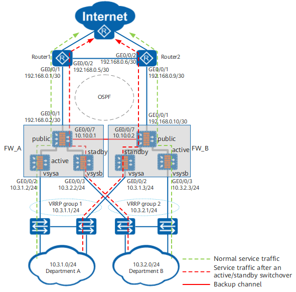
Data Planning
Item |
Data |
Description |
|---|---|---|
Interfaces |
Interface number: GigabitEthernet 0/0/1 IP address: 192.168.0.2/30 Security zone: Untrust |
Upstream interface of public system public |
Interface number: GigabitEthernet 0/0/2 IP address: 10.3.1.2/24 Security zone: Trust |
Downstream interface of virtual system vsysa |
|
Interface number: GigabitEthernet 0/0/3 IP address: 10.3.2.2/24 Security zone: Trust |
Downstream interface of virtual system vsysb |
|
Interface number: GigabitEthernet 0/0/7 IP address: 10.10.0.1/24 Security zone: DMZ |
Heartbeat interface |
|
VRRP groups |
VRRP group 1: 10.3.1.1/24 active |
- |
VRRP group 2: 10.3.2.1/24 standby |
- |
|
Routes |
Blackhole route Destination IP address: 1.1.1.1/32 |
Blackhole route configured for the NAT address pool of public system public to prevent route loops |
OSPF 100 Advertised network segment: 192.168.0.0/30 Static routes imported |
OSPF configuration of public system public |
Item |
Data |
Description |
|---|---|---|
Interfaces |
Interface number: GigabitEthernet 0/0/1 IP address: 192.168.0.10/30 Security zone: Untrust |
Upstream interface of public system public |
Interface number: GigabitEthernet 0/0/2 IP address: 10.3.1.3/24 Security zone: Trust |
Downstream interface of virtual system vsysa |
|
Interface number: GigabitEthernet 0/0/3 IP address: 10.3.2.3/24 Security zone: Trust |
Downstream interface of virtual system vsysb |
|
Interface number: GigabitEthernet 0/0/7 IP address: 10.10.0.2/24 Security zone: DMZ |
Heartbeat interface |
|
VRRP groups |
VRRP group 1: 10.3.1.1/24 standby |
- |
VRRP group 2: 10.3.2.1/24 active |
- |
|
Routes |
Blackhole route Destination IP address: 1.1.1.1/32 |
Blackhole route configured for the NAT address pool of public system public to prevent route loops |
OSPF 100 Advertised network segment: 192.168.0.8/30 Static routes imported |
OSPF configuration of public system public |
Item |
Data |
Description |
|---|---|---|
Interfaces |
Interface number: GigabitEthernet 0/0/1 IP address: 192.168.0.1/30 |
Connecting to FW public system public |
Interface number: GigabitEthernet 0/0/2 IP address: 192.168.0.5/30 |
Connecting to Router2 |
|
OSPF |
OSPF 100 Advertised network segment: 192.168.0.0/30 Default routes imported |
- |
Item |
Data |
Description |
|---|---|---|
Interfaces |
Interface number: GigabitEthernet 0/0/1 IP address: 192.168.0.9/30 |
Connecting to FW public system public |
Interface number: GigabitEthernet 0/0/2 IP address: 192.168.0.6/30 |
Connecting to Router1 |
|
OSPF |
OSPF 100 Advertised network segment: 192.168.0.8/30 Default routes imported |
- |
Configuration Roadmap
- Create different virtual systems on FW_A and FW_B to isolate networks of different departments.
- Configure mutual communication between the virtual systems and the public system on FW_A and FW_B so that different virtual systems can share the interface of the public system to access the Internet.
- The service interfaces of FW_A and FW_B work at Layer 3 in load balancing mode, connect to upstream routers, and run OSPF. Therefore, you need to configure OSPF and VGMP groups to monitor service interfaces. That is, configure OSPF-based hot standby in load balancing mode. The service interfaces also connect to downstream switches. Therefore, you need to configure VRRP groups. In addition, you shall also complete basic configurations, such as configuring heartbeat interfaces and enabling the hot standby function.
- Configure a Link-Group on FW_A and FW_B and add the upstream interface of the public system and the downstream interfaces of the virtual systems to this Link-Group to ensure that the upstream and downstream interfaces are in the same state.
- After hot standby is deployed, configure security policies and NAT policies for intranet users to access the Internet on FW_A. You do not need to configure the policies on FW_B in that the policies can be automatically synchronized from FW_A.
Procedure
- Create virtual systems vsysa and vsysb and assign interfaces to them.

The virtual system names and IDs on FW_A and FW_B must be the same. After the virtual systems are created, you can choose and check whether the virtual system names and configuration sequences are consistent in Virtual System List.
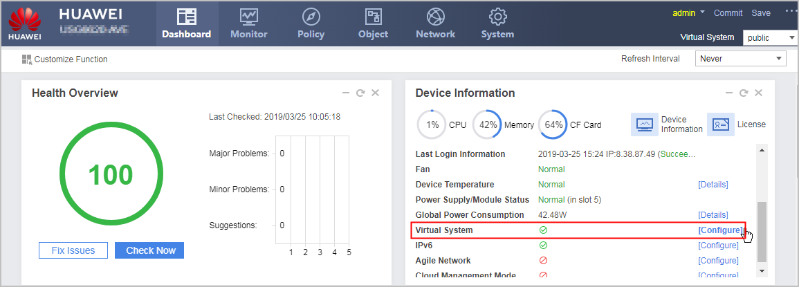
- Click Dashboard on the main menu of FW_A. In Device Information area, click Configure on the line of Virtual System to enable the virtual system function.
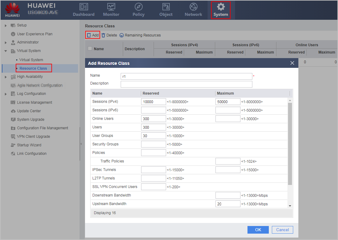
- On FW_A, choose and click Add to configure a resource class.
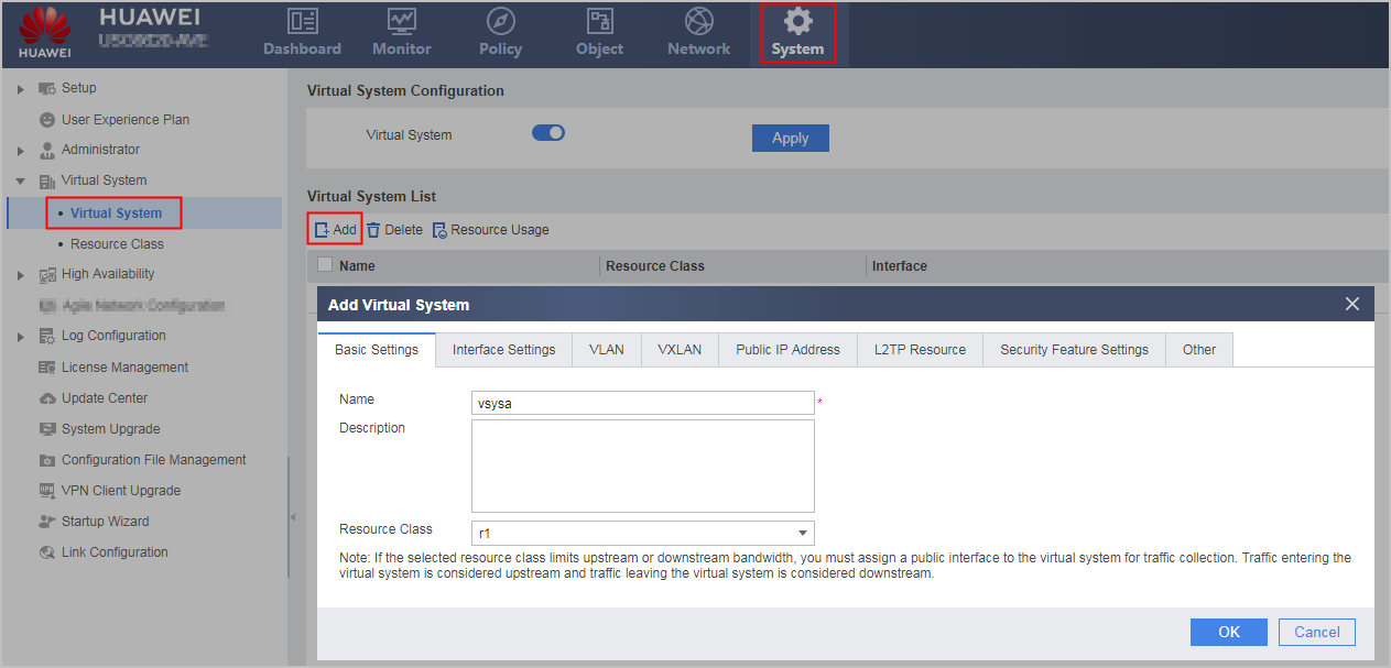
- On FW_A, choose to create virtual systems vsysa and vsysb and allocate interfaces and resources to them.
Click Add, select the Basic Settings tab, enter the virtual system name and select the resource class r1. The following part uses vsysa as an example.
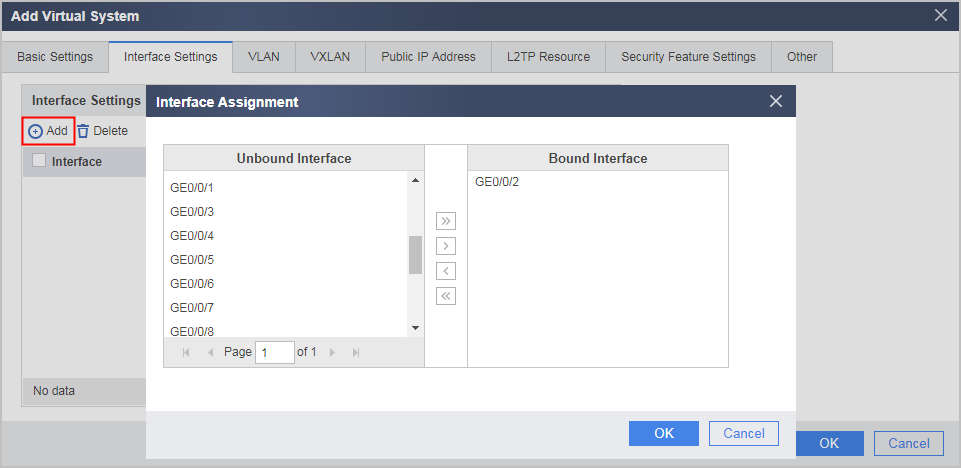
Select the Interface Settings tab to allocate interfaces GE0/0/2 and GE0/0/3 to the virtual systems vsysa and vsysb respectively. The following part uses vsysa as an example.
- Click Dashboard on the main menu of FW_A. In Device Information area, click Configure on the line of Virtual System to enable the virtual system function.
- Configure interfaces.
- Configure the interfaces of virtual system vsysa on FW_A.
On FW_A, choose , click Edit on the line of an interface to configure the downstream interface and virtual interface Virtual-if1 of virtual system vsysa. The IP address for virtual interface Virtual-if1 can be any value that is not in conflict with the IP addresses of other interfaces.
The ID of a virtual interface is automatically assigned based on existing IDs in the system. Therefore, in actual configurations, the interface might not be Virtual-if1. You can view the mapping between the virtual system and virtual interface in Interface List.
Interface
GigabitEthernet 0/0/2
Virtual-if1
Virtual System
vsysa
vsysa
Security Zone
trust
untrust
IP Address
10.3.1.2/24
172.16.1.1/24
- Configure the interfaces of virtual system vsysa on FW_A.
- Configures static routes.
- Configure static routes on FW_A.
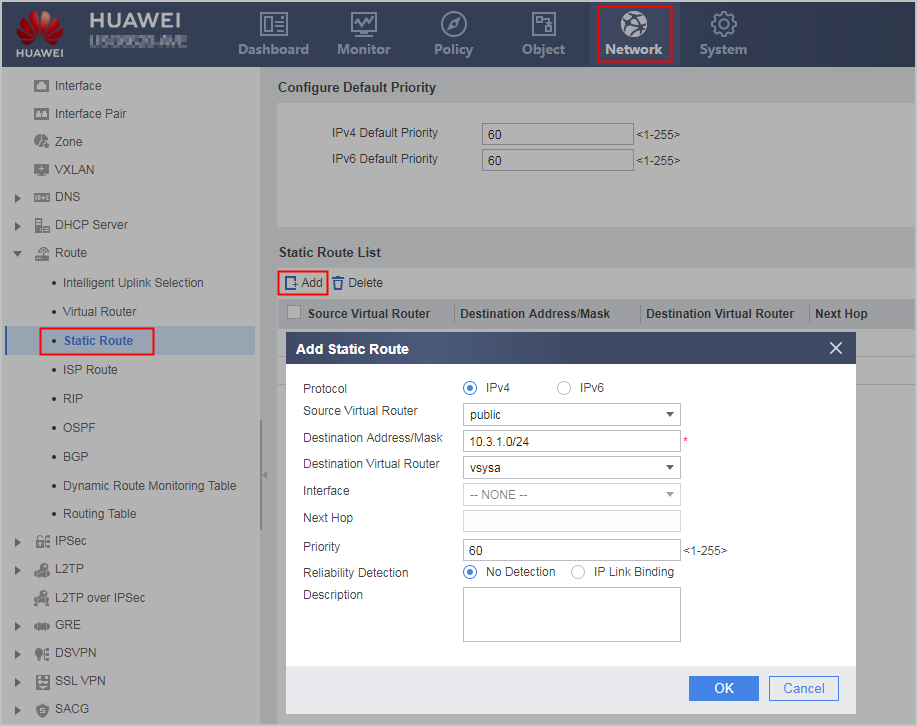
In the public system, choose and click Add to configure a static route to guide the return traffic from the Internet to employees in vsysa.
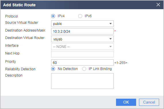
By referring to the preceding procedure, configure a static route to guide the return traffic from the Internet to employees in vsysb.
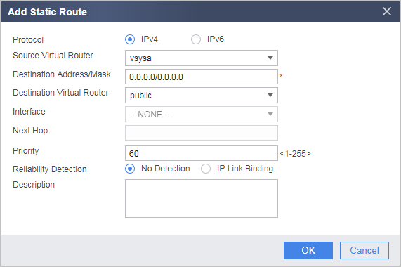
By referring to the preceding procedure, configure a static route to guide the Internet access traffic from employees in vsysa to the public system.
In this example, the network topology and route configuration are simplified. If vsysa only needs to communicate with the Internet, set Destination Address/Mask to 0.0.0.0/0.0.0.0. That is, all packets are sent to the public system. In practice, for accurate routing information, you shall set Destination Address/Mask to a specific Internet address range that the intranet users are allowed to access. Incorrect route configuration may result in communication failure of multiple LANs connected with vsysa.
By referring to the preceding procedure, configure a static route to guide the Internet access traffic from employees in vsysb to the public system.
In this example, the network topology and route configuration are simplified. If vsysb only needs to communicate with the Internet, set Destination Address/Mask to 0.0.0.0/0.0.0.0. That is, all packets are sent to the public system. In practice, for accurate routing information, you shall set Destination Address/Mask to a specific Internet address range that the intranet users are allowed to access. Incorrect route configuration may result in communication failure of multiple LANs connected with vsysb.
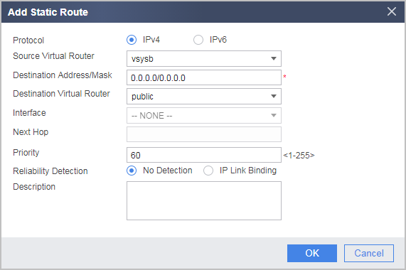
- Configure static routes on FW_A.
- Configure OSPF.
- On FW_A, choose , click Add to create OSPF 100, click
 on the line of OSPF 100, click Add, and set the following area parameters.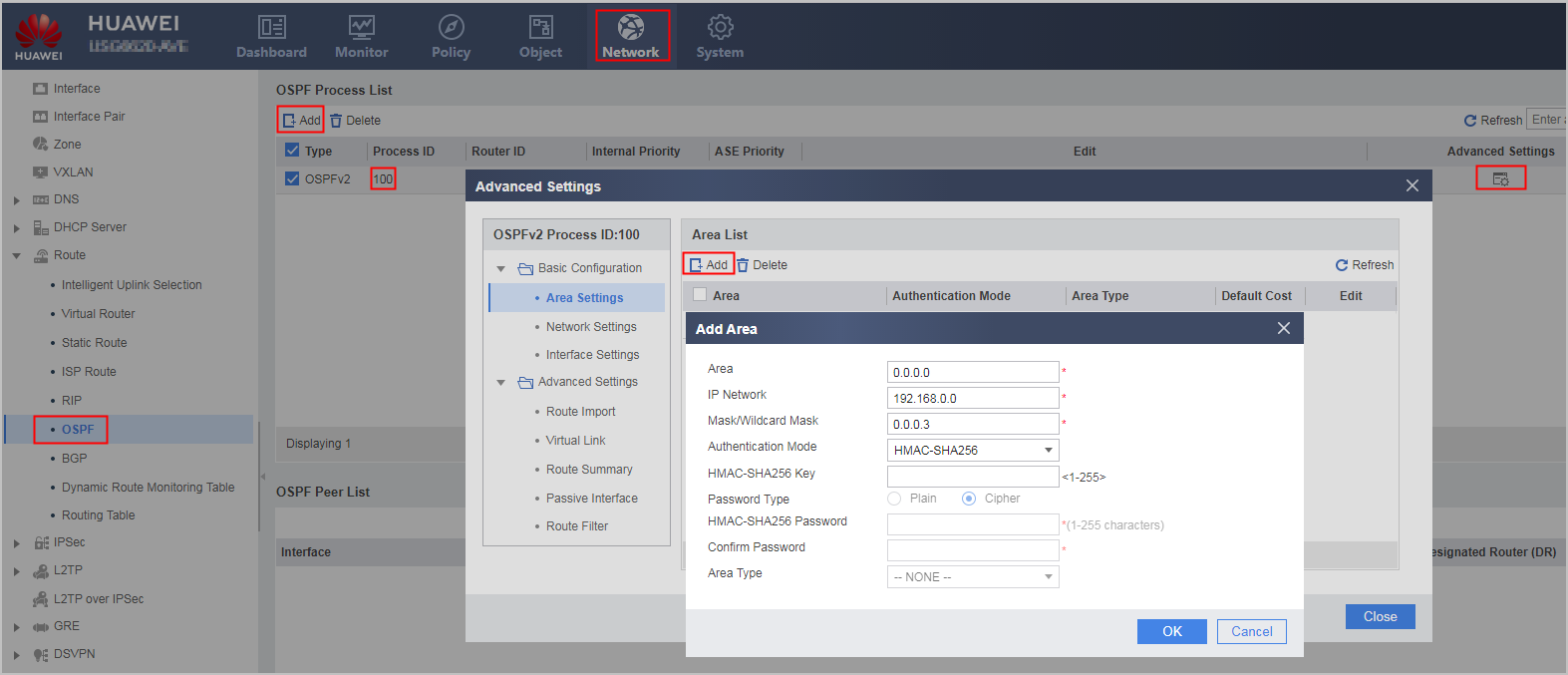
- By referring to the preceding procedure, configure OSPF on FW_B.
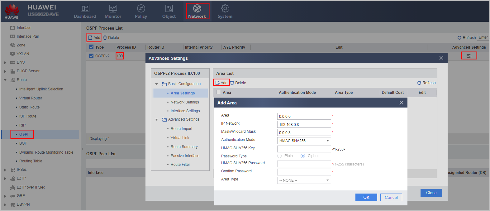
- On FW_A, choose , click Add to create OSPF 100, click
- Configure the Link-Group function to ensure that the upstream and downstream interfaces are in the same state.
- On FW_A, choose , click
 on the line of Link-Group1, and set the following parameters. Add the public system interface (upstream interface) and virtual system interfaces (downstream interfaces) to the same Link-Group on FW_A.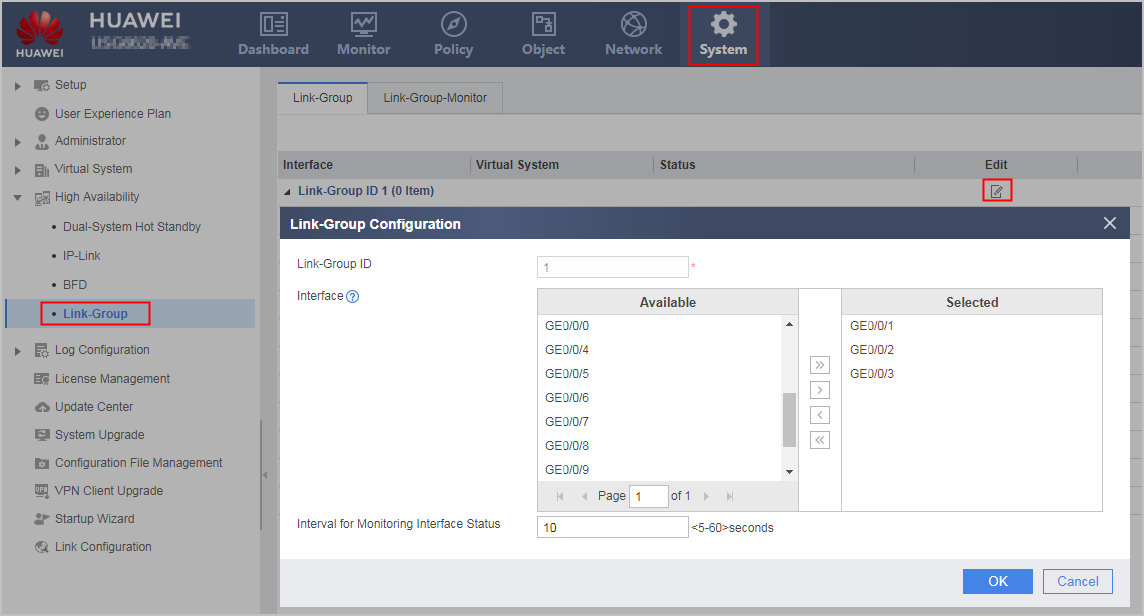
- On FW_A, choose , click
- Configure hot standby.
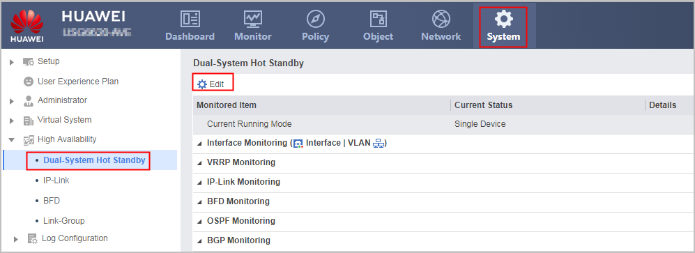
- On FW_A, choose , click Edit, select the Enable check box following Dual-System Hot Standby, and set the following parameters.
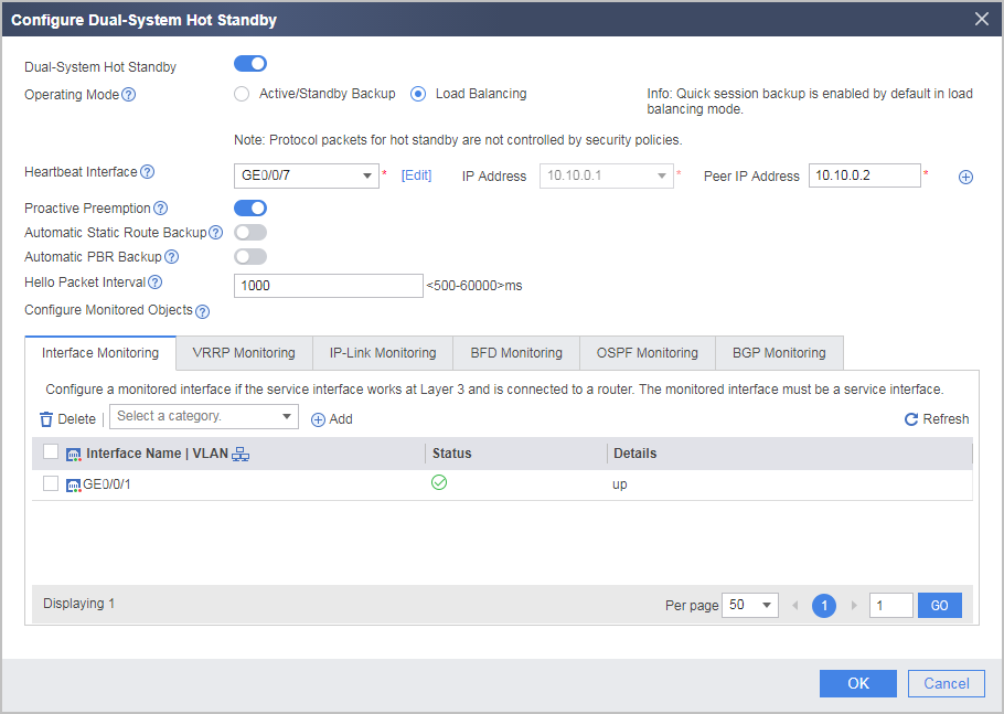
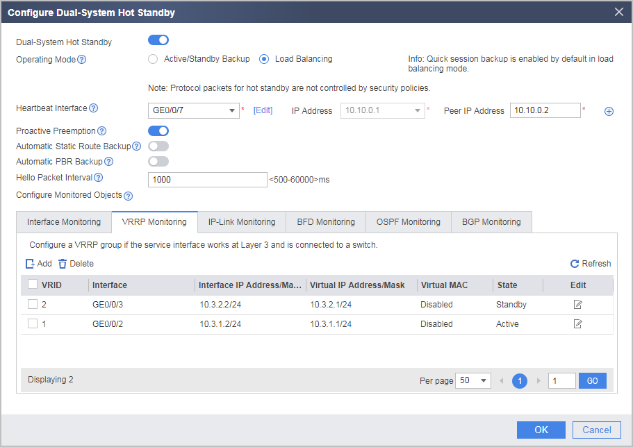
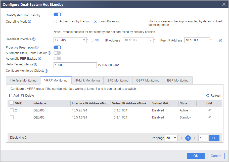
- On FW_B, set the following hot standby parameters.
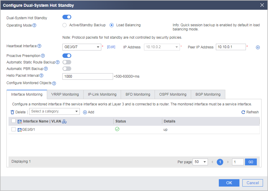
- To prevent port conflicts in address translation on the FWs in load balancing mode, configure available port ranges on FW_A and FW_B. Currently, the configuration cannot be performed on the web UI. Click CLI Console in the lower right corner of the page to display the CLI configuration page and configure it on the CLI.
In the hot standby load balancing scenario, If NAPT is configured, the FWs may have conflicting public ports. To prevent such conflicts, configure respective NAT resources (including public IP addresses and ports) for the FWs. You can run the hrp nat resource primary-group command on the active FW. The standby FW will automatically generate the hrp nat resource secondary-group command (if you run the hrp nat resource secondary-group command on the active FW, the standby FW will automatically generate the hrp nat resource primary-group command).
Perform the following configuration on FW_A:
HRP_M[FW_A] hrp nat resource primary-groupPerform the following configuration on FW_B:
HRP_S[FW_B] hrp nat resource secondary-group
- On FW_A, choose , click Edit, select the Enable check box following Dual-System Hot Standby, and set the following parameters.
- Configure security policies.
Security policies can be backed up. That is, policies configured on FW_A can be automatically synchronized to FW_B. If you have configured security policies separately on FW_A and FW_B before configuring hot standby, ensure that their configurations and the sequences in which they are configured are the same on FW_A and FW_B. Otherwise, services may become abnormal after active/standby switchover.
- Configure a NAT policy.
On FW_A, configure a NAT policy for the public system to allow intranet users to access the Internet. The NAT policy configured on FW_A can be automatically synchronized to FW_B.
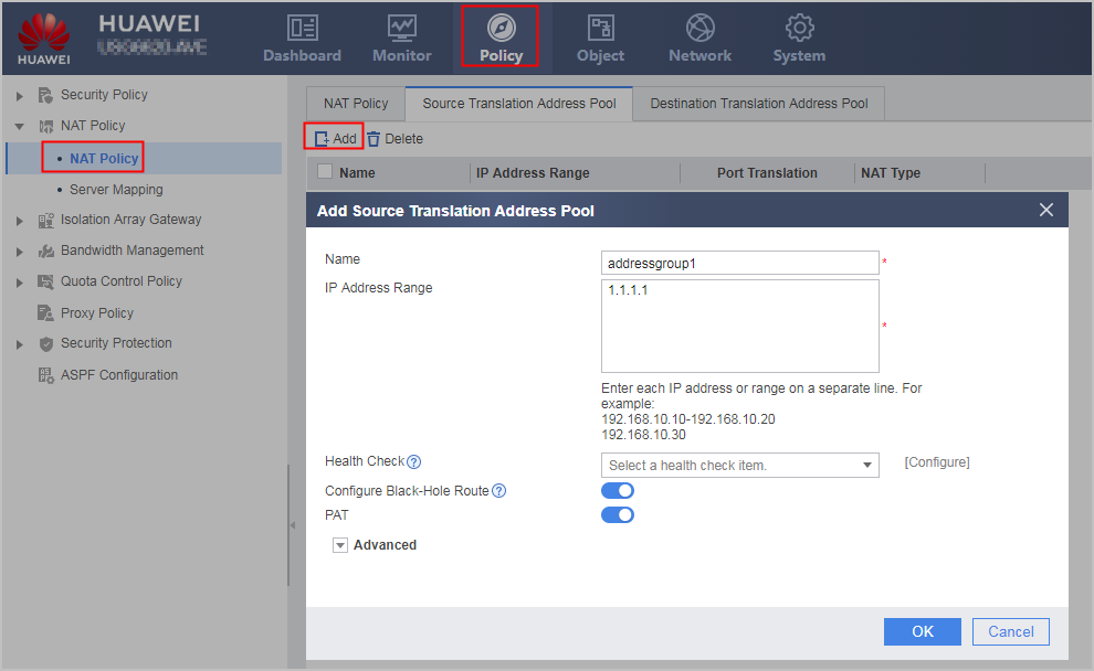
- Choose , click Add and configure a NAT address pool based on the following parameter values.
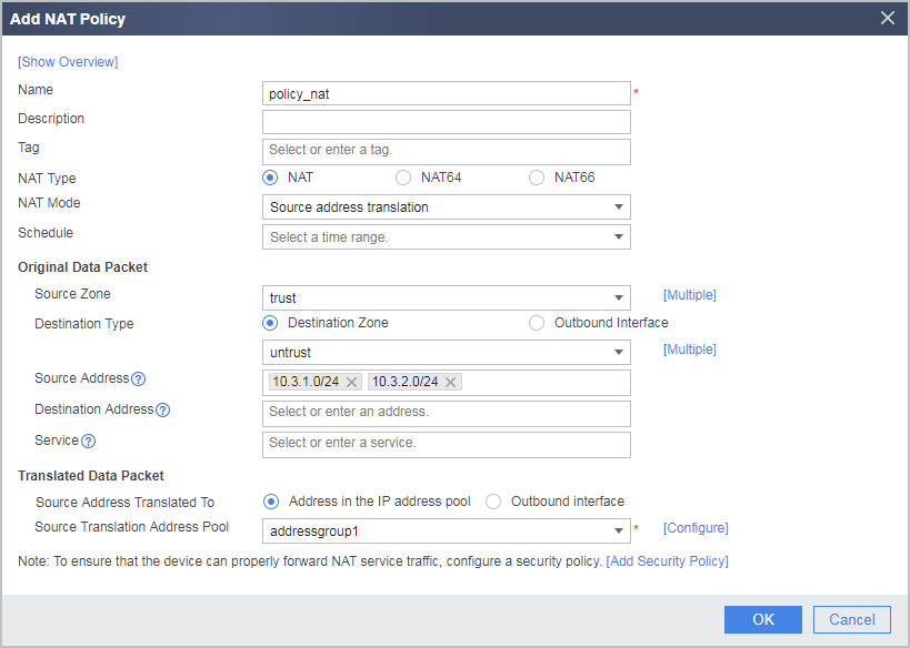
- Choose , click Add and configure a NAT policy based on the following parameter values.
- Choose , click Add and configure a NAT address pool based on the following parameter values.
- Configure routers.
The following part uses Huawei routers to illustrate the configuration.
# Configure Router1.
[router1] interface GigabitEthernet 0/0/1
[router1-GigabitEthernet0/0/1] ip address 192.168.0.1 30
[router1-GigabitEthernet0/0/1] quit
[router1] interface GigabitEthernet 0/0/2
[router1-GigabitEthernet0/0/2] ip address 192.168.0.5 30
[router1-GigabitEthernet0/0/2] quit
[router1] ospf 100
[router1-ospf-100] default-route-advertise
[router1-ospf-100] area 0
[router1-ospf-100-area-0.0.0.0] network 192.168.0.0 0.0.0.3
[router1-ospf-100-area-0.0.0.0] quit
[router1-ospf-100] quit
# Configure Router2.
[router2] interface GigabitEthernet 0/0/1
[router2-GigabitEthernet0/0/1] ip address 192.168.0.9 30
[router2-GigabitEthernet0/0/1] quit
[router2] interface GigabitEthernet 0/0/2
[router2-GigabitEthernet0/0/2] ip address 192.168.0.6 30
[router2-GigabitEthernet0/0/2] quit
[router2] ospf 100
[router2-ospf-100] default-route-advertise
[router2-ospf-100] area 0
[router2-ospf-100-area-0.0.0.0] network 192.168.0.8 0.0.0.3
[router2-ospf-100-area-0.0.0.0] quit
[router2-ospf-100] quit
Verification
- On FW_A and FW_B, choose to view the operating status of hot standby.
- Normally, the Current Running Mode of FW_A is Load Balancing and the Current Status is Active. The Current Running Mode of FW_B is Load Balancing and the Current Status is Active. This shows that traffic is forwarded by both FW_A and FW_B.
- When FW_A goes faulty, the Current Running Mode of FW_A is Active/Standby Backup and the Current Status is Standby. The Current Running Mode of FW_B is Active/Standby Backup and the Current Status is Active. This shows that traffic is forwarded by FW_B.
Access from the private network to the Internet succeeds. In the public system and virtual system of FW_A and FW_B, choose to check sessions. If both FWs have sessions with backup flags, sessions have been successfully backed up after hot standby is configured.
Ping an IP address on the Internet from an intranet PC and remove the network cable from GigabitEthernet 0/0/2 on FW_A. FW status switchover occurs, the status of FW_A changes from Active to Standby, and no ping packets are discarded. Then, in the public system of FW_A, choose . The status of upstream interface GigabitEthernet 0/0/1 also changes to Down, which is consistent with that of GigabitEthernet 0/0/2.
Then insert the network cable back to GigabitEthernet 0/0/2 on FW_A. The status of FW_A changes from Standby to Active, no ping packets are discarded, and the interfaces in the Link-Group become Up again.
Ping an IP address on the Internet from an intranet PC and remove the network cable from GigabitEthernet 0/0/3 on FW_B. FW status switchover occurs, the status of FW_B changes from Active to Standby, and no ping packets are discarded. Then, in the public system of FW_B, choose . The status of upstream interface GigabitEthernet 0/0/1 also changes to Down, which is consistent with that of GigabitEthernet 0/0/3.
Then insert the network cable back to GigabitEthernet 0/0/3 on FW_B. The status of FW_B changes from Standby to Active, no ping packets are discarded, and the interfaces in the Link-Group become Up again.
Configuration Scripts
Configuration script of the public system:
FW_A |
FW_B |
|---|---|
# hrp enable hrp interface GigabitEthernet 0/0/7 remote 10.10.0.2 hrp track interface GigabitEthernet 0/0/1 hrp mirror session enable hrp nat resource primary-group # interface GigabitEthernet 0/0/1 ip address 192.168.0.2 255.255.255.252 link-group 1 # interface GigabitEthernet 0/0/2 ip binding vpn-instance vsysa ip address 10.3.1.2 255.255.255.0 vrrp vrid 1 virtual-ip 10.3.1.1 active link-group public 1 # interface GigabitEthernet 0/0/3 ip binding vpn-instance vsysb ip address 10.3.2.2 255.255.255.0 vrrp vrid 2 virtual-ip 10.3.2.1 standby link-group public 1 # interface GigabitEthernet 0/0/7 ip address 10.10.0.1 255.255.255.0 # interface Virtual-if0 ip address 172.16.0.1 255.255.255.0 # interface Virtual-if1 ip address 172.16.1.1 255.255.255.0 # interface Virtual-if2 ip address 172.16.2.1 255.255.255.0 # firewall zone trust set priority 85 add interface GigabitEthernet 0/0/2 add interfac Virtual-if0 # firewall zone dmz set priority 50 add interface GigabitEthernet 0/0/7 # firewall zone untrust set priority 5 add interface GigabitEthernet 0/0/1 # vsys enable resource-class r0 resource-class r1 resource-item-limit session reserved-number 10000 maximum 50000 resource-item-limit bandwidth 20 outbound resource-item-limit policy reserved-number 300 resource-item-limit user reserved-number 300 resource-item-limit user-group reserved-number 30 # vsys name vsysa assign interface GigabitEthernet 0/0/2 assign resource-class r1 # vsys name vsysb assign interface GigabitEthernet 0/0/3 assign resource-class r1 # ip route-static 10.3.1.0 255.255.255.0 vpn-instance vsysa ip route-static 10.3.2.0 255.255.255.0 vpn-instance vsysb # ospf 100 import-route static area 0.0.0.0 network 192.168.0.0 0.0.0.3 # security-policy rule name policy_sec source-zone trust destination-zone untrust action permit # nat address-group addressgroup1 mode pat route enable section 0 1.1.1.1 1.1.1.1 # nat-policy rule name policy_nat source-zone trust destination-zone untrust source-address 10.3.1.0 24 source-address 10.3.2.0 24 action source-nat address-group addressgroup1 |
# hrp enable hrp interface GigabitEthernet 0/0/7 remote 10.10.0.1 hrp track interface GigabitEthernet 0/0/1 hrp mirror session enable hrp nat resource secondary-group # interface GigabitEthernet 0/0/1 ip address 192.168.0.10 255.255.255.252 link-group 1 # interface GigabitEthernet 0/0/2 ip binding vpn-instance vsysa ip address 10.3.1.3 255.255.255.0 vrrp vrid 1 virtual-ip 10.3.1.1 standby link-group public 1 # interface GigabitEthernet 0/0/3 ip binding vpn-instance vsysb ip address 10.3.2.3 255.255.255.0 vrrp vrid 2 virtual-ip 10.3.2.1 active link-group public 1 # interface GigabitEthernet 0/0/7 ip address 10.10.0.2 255.255.255.0 # interface Virtual-if0 ip address 172.16.0.2 255.255.255.0 # interface Virtual-if1 ip address 172.16.1.2 255.255.255.0 # interface Virtual-if2 ip address 172.16.2.2 255.255.255.0 # firewall zone trust set priority 85 add interface GigabitEthernet 0/0/2 add interfac Virtual-if0 # firewall zone dmz set priority 50 add interface GigabitEthernet 0/0/7 # firewall zone untrust set priority 5 add interface GigabitEthernet 0/0/1 # vsys enable resource-class r0 resource-class r1 resource-item-limit session reserved-number 10000 maximum 50000 resource-item-limit bandwidth 20 outbound resource-item-limit policy reserved-number 300 resource-item-limit user reserved-number 300 resource-item-limit user-group reserved-number 30 # vsys name vsysa assign interface GigabitEthernet 0/0/2 assign resource-class r1 # vsys name vsysb assign interface GigabitEthernet 0/0/3 assign resource-class r1 # ip route-static 10.3.1.0 255.255.255.0 vpn-instance vsysa ip route-static 10.3.2.0 255.255.255.0 vpn-instance vsysb # ospf 100 import-route static area 0.0.0.0 network 192.168.0.8 0.0.0.3 # security-policy rule name policy_sec source-zone trust destination-zone untrust action permit # nat address-group addressgroup1 mode pat route enable section 0 1.1.1.1 1.1.1.1 # nat-policy rule name policy_nat source-zone trust destination-zone untrust source-address 10.3.1.0 24 source-address 10.3.2.0 24 action source-nat address-group addressgroup1 |
Configuration script of vsysa:
FW_A |
FW_B |
|---|---|
# switch vsys vsysa # interface GigabitEthernet 0/0/2 ip binding vpn-instance vsysa ip address 10.3.1.2 255.255.255.0 vrrp vrid 1 virtual-ip 10.3.1.1 active link-group public 1 # interface Virtual-if1 ip address 172.16.1.1 255.255.255.0 # firewall zone trust set priority 85 add interface GigabitEthernet 0/0/2 # firewall zone untrust set priority 5 add interface Virtual-if1 # ip route-static 0.0.0.0 0.0.0.0 public # security-policy rule name vsysa_to_vsysb source-zone trust destination-zone untrust source-address 10.3.1.0 24 destination-address 10.3.2.0 24 action deny rule name policy_sec source-zone trust destination-zone untrust source-address 10.3.1.0 24 action permit |
# switch vsys vsysa # interface GigabitEthernet 0/0/2 ip binding vpn-instance vsysa ip address 10.3.1.3 255.255.255.0 vrrp vrid 1 virtual-ip 10.3.1.1 standby link-group public 1 # interface Virtual-if1 ip address 172.16.1.2 255.255.255.0 # firewall zone trust set priority 85 add interface GigabitEthernet 0/0/2 # firewall zone untrust set priority 5 add interface Virtual-if1 # ip route-static 0.0.0.0 0.0.0.0 public # security-policy rule name vsysa_to_vsysb source-zone trust destination-zone untrust source-address 10.3.1.0 24 destination-address 10.3.2.0 24 action deny rule name policy_sec source-zone trust destination-zone untrust source-address 10.3.1.0 24 action permit |
Configuration script of vsysb:
FW_A |
FW_B |
|---|---|
# switch vsys vsysb # interface GigabitEthernet 0/0/3 ip binding vpn-instance vsysb ip address 10.3.2.2 255.255.255.0 vrrp vrid 2 virtual-ip 10.3.2.1 standby link-group public 1 # interface Virtual-if2 ip address 172.16.2.1 255.255.255.0 # firewall zone trust set priority 85 add interface GigabitEthernet 0/0/3 # firewall zone untrust set priority 5 add interface Virtual-if2 # ip route-static 0.0.0.0 0.0.0.0 public # security-policy rule name vsysb_to_vsysa source-zone trust destination-zone untrust source-address 10.3.2.0 24 destination-address 10.3.1.0 24 action deny rule name policy_sec source-zone trust destination-zone untrust source-address 10.3.2.0 24 action permit |
# switch vsys vsysb # interface GigabitEthernet 0/0/3 ip binding vpn-instance vsysb ip address 10.3.2.3 255.255.255.0 vrrp vrid 2 virtual-ip 10.3.2.1 active link-group public 1 # interface Virtual-if2 ip address 172.16.2.2 255.255.255.0 # firewall zone trust set priority 85 add interface GigabitEthernet 0/0/3 # firewall zone untrust set priority 5 add interface Virtual-if2 # ip route-static 0.0.0.0 0.0.0.0 public # security-policy rule name vsysb_to_vsysa source-zone trust destination-zone untrust source-address 10.3.2.0 24 destination-address 10.3.1.0 24 action deny rule name policy_sec source-zone trust destination-zone untrust source-address 10.3.2.0 24 action permit |